
High voltage regulated power supply

a high-voltage regulated, power supply technology, applied in the direction of electric variable regulation, instruments, electrical apparatuses, etc., can solve the problems of power supply instability and oscillation, and achieve the effect of minimising the propagation delay in the control circui

Inactive Publication Date: 2011-07-21
THOMAS ROGOFF AUDIO
View PDF2 Cites 8 Cited by
  • Summary
  • Abstract
  • Description
  • Claims
  • Application Information

AI Technical Summary

Benefits of technology

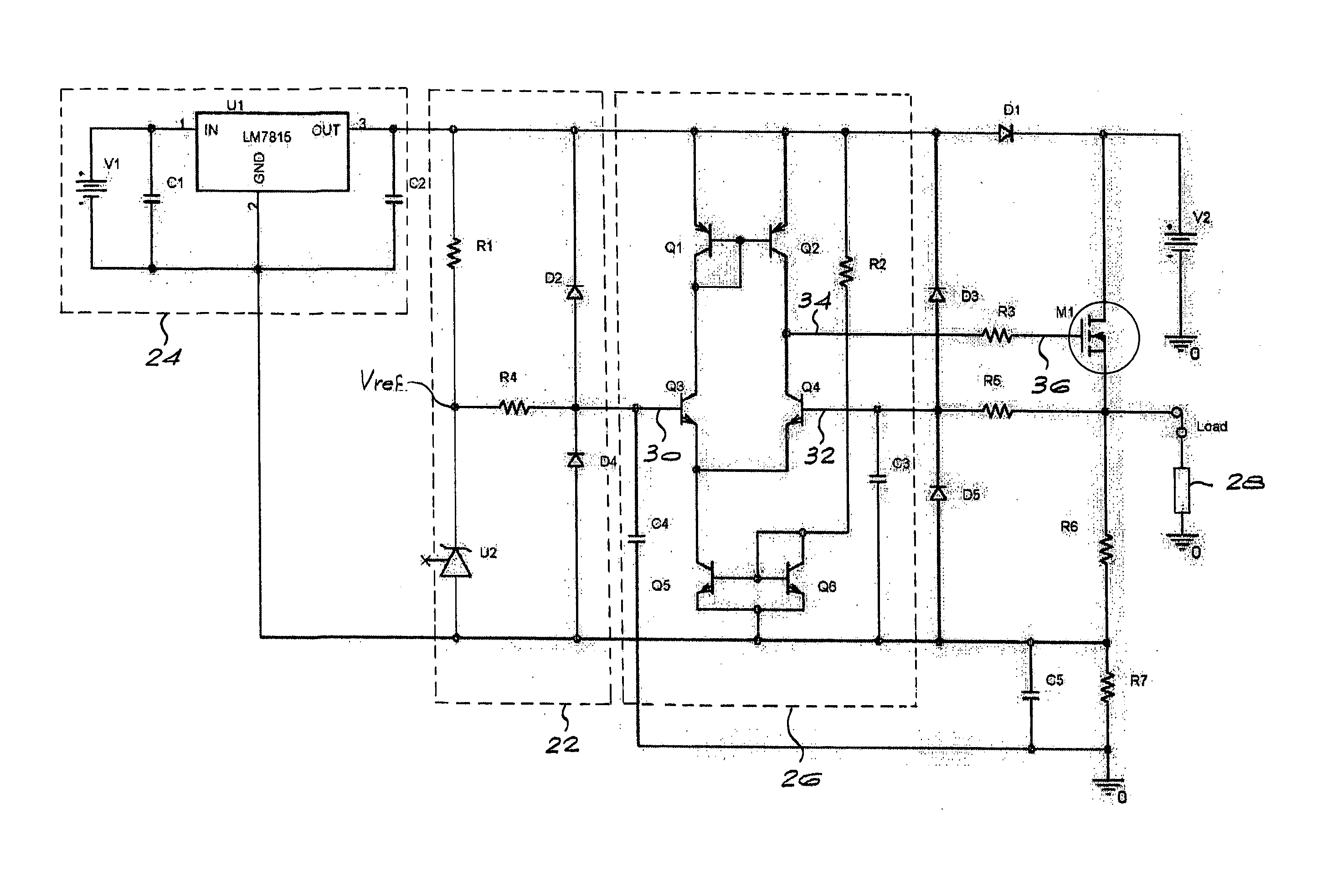
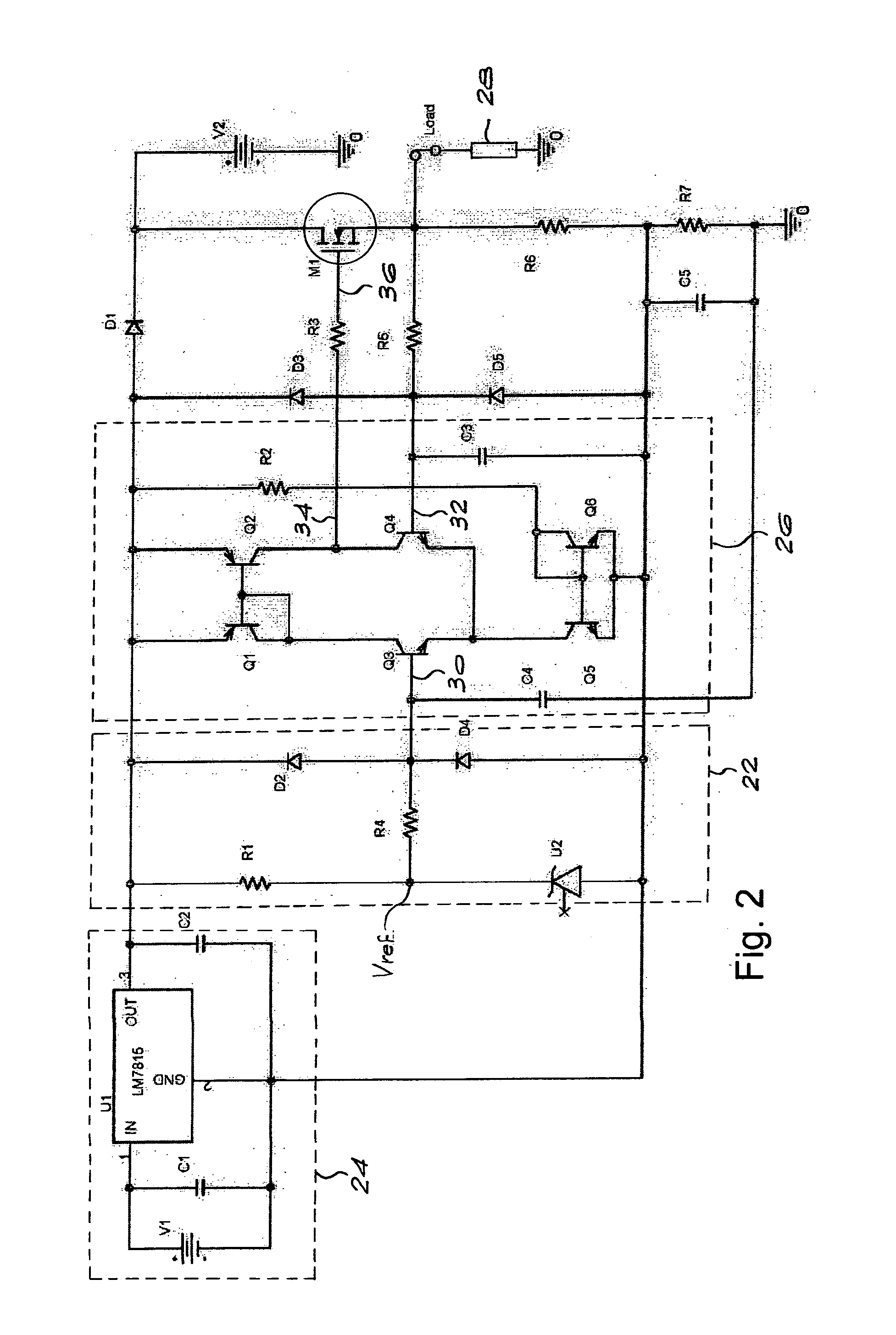
[0007]a control circuit arranged to compare an output voltage at the load with the reference voltage, the control circuit including a comparator comprising a long-tailed transistor pair having a first input to which the reference voltage is applied, a second input to which the output voltage is applied, and an output connected to an input terminal of the output device, the control circuit being arranged to apply a correction signal to the output device via a single semiconductor junction to regulate the output voltage, thereby to minimise propagation delay in the control circuit.
[0011]Preferably, the comparator includes both the first and second current mirrors, configured to enhance the gain and slew rate of the comparator.

Problems solved by technology

However, regulators based on operational amplifiers generally have a limited ability to respond to rapidly varying loads, which can lead to highly undesirable instability and oscillation of the power supply.

Method used


Image

  • High voltage regulated power supply
  • High voltage regulated power supply
  • High voltage regulated power supply

Examples


Embodiment Construction

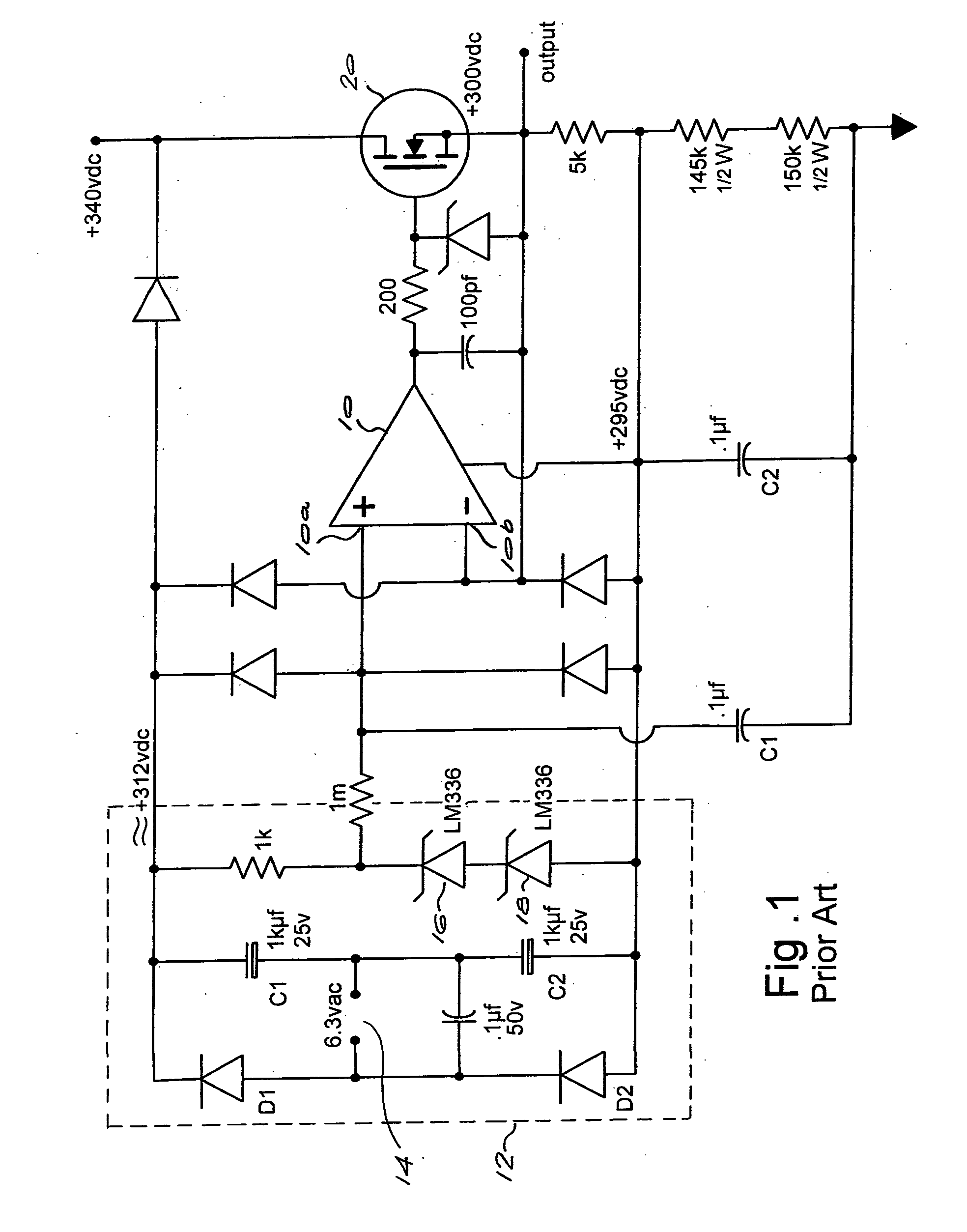
[0016]FIG. 1 is a circuit diagram showing a prior art regulated power supply circuit. The known regulated power supply circuit is based on an operational amplifier 10, configured as a comparator. The operational amplifier 10 has a non-inverting input 10a to which a reference voltage is applied and an inverting input 10b to which a feedback signal, derived from the voltage regulator output voltage, is applied.

[0017]The reference voltage is derived from a voltage reference circuit 12 comprising a 6.3V AC source 14, rectifying diodes D1 and D2 and smoothing capacitors C1 and C2. The voltage reference circuit further includes voltage reference diodes 16 and 18.

[0018]A correction signal is generated at the output of the operational amplifier 10, arising from differences between the reference voltage applied to the non-inverting input 10a and the feedback signal applied to the inverting input 10b, and is applied to the gate of a power FET 20.

[0019]The prior art circuit is satisfactory for...


PUM


Abstract

A regulated power supply circuit includes a voltage reference circuit arranged to generate a reference voltage and an output device responsive to a control signal to supply a load from a voltage source. A control circuit is arranged to compare an output voltage at the load with the reference voltage. The control circuit includes a comparator comprising a long-tailed transistor pair having a first input to which the reference voltage is applied, a second input to which the output voltage is applied, and an output connected to an input terminal of the output device. The control circuit applies a correction signal to the output device via a single semiconductor junction to regulate the output voltage, thereby minimising propagation delay in the control circuit. The circuit may include a primary voltage regulator arranged to supply the control circuit at a lower voltage than that of the voltage source.

Description

BACKGROUND OF THE INVENTION[0001]THIS invention relates to a regulated power supply circuit which can be used, in particular, to supply a gain stage in an audio amplifier circuit.[0002]Generally in high power audio amplifiers, high DC voltages are required for the gain stage and it is advisable that the power supply used is regulated. The load imposed on the power supply by such a gain stage can vary rapidly in terms of both amplitude and frequency. Conventionally, a regulated power supply based on an operational amplifier is used in such applications. However, regulators based on operational amplifiers generally have a limited ability to respond to rapidly varying loads, which can lead to highly undesirable instability and oscillation of the power supply.[0003]It is an object of the present invention, to provide an alternative regulated power supply circuit.SUMMARY OF THE INVENTION[0004]According to the invention there is provided a regulated power supply circuit comprising:[0005]a...

Claims


Application Information

Patent Timeline
Patent Type & Authority Applications(United States)
IPC IPC(8): G05F1/575
CPCG05F1/56H03F2203/45676H03F3/45475H03F2200/78H03F2203/45102H03F2203/45116H03F2203/45136H03F2203/45142H03F2203/45158H03F2203/45188H03F2203/45322H03F2203/45512H03F2203/45518H03F2203/45568H03F2203/45646H03F3/45085
Inventor THOMAS, CLIVE
Owner THOMAS ROGOFF AUDIO
Learn More