System for Blood Flow Velocity Determination using MR Imaging

a technology of flow velocity and imaging, applied in the field of system for blood flow velocity determination in mr imaging, can solve the problems of difficult manual alignment of these axes, high cost, and often underestimated peak velocity of flow jets by methods, so as to improve the speed and precision of mr data acquisition workflow, the effect of improving the accuracy of peak velocity measurements

Active Publication Date: 2011-07-21
SIEMENS MEDICAL SOLUTIONS USA INC
View PDF5 Cites 5 Cited by
  • Summary
  • Abstract
  • Description
  • Claims
  • Application Information

AI Technical Summary

Benefits of technology

[0005]A system provides automatic and precise alignment of a velocity-encoding axis of a real-time single-dimensional phase-contrast sequence with a principle axis of a blood flow jet, improving the accuracy of peak velocity measurements as well as the speed and precision of an MR data acquisition workflow. A system for blood flow velocity determination in MR imaging comprises an MR imaging system. The MR imaging system acquires a three dimensional (3D) MR imaging dataset of a patient anatomical volume of interest and a one dimensional (1D) MR imaging dataset within the volu

Problems solved by technology

However, this method often underestimates peak velocity of flow jets due in part to reliance on subjective alignment of a velocity-encoding axis employed by a pulse sequence used for MR data acquisition, with the principle axis of the jet, and also due in part to using insufficient temporal resolution when sampling blood flow data.
Manual alignment of these axes may be difficult, particularly as post-stenotic jets frequently exhibit a degree of eccentricity and can change direction throughout a cardiac cycle.
Obtaining sufficiently high temporal resolution in MR image data acquisition is difficult, particularly as lower temporal re

Method used


Image

  • System for Blood Flow Velocity Determination using MR Imaging
  • System for Blood Flow Velocity Determination using MR Imaging
  • System for Blood Flow Velocity Determination using MR Imaging

Examples


Embodiment Construction

[0010]A system provides automatic accurate alignment of a velocity-encoding axis of a real-time single-dimensional phase-contrast sequence with a principle axis of a blood flow jet, improving the accuracy of peak velocity measurements as well as the speed and precision MR image data acquisition. In one embodiment the system provides an optimized workflow for accurate determination of peak velocity in blood flow jets using vector analysis of phase-contrast data having multiple spatial-encoding dimensions and multiple velocity-encoding dimensions to automatically and precisely align a velocity-encoding axis of a real-time single-dimensional phase-contrast sequence with the principle axis of the flow jet. The system automatically identifies real-time single-dimensional phase-contrast data in an optimal location and orientation to clinically assess blood flow jets from intra-cardiac valve pathologies such as stenosis and regurgitation, vascular pathologies such as coarctations and surgi...


PUM


Abstract

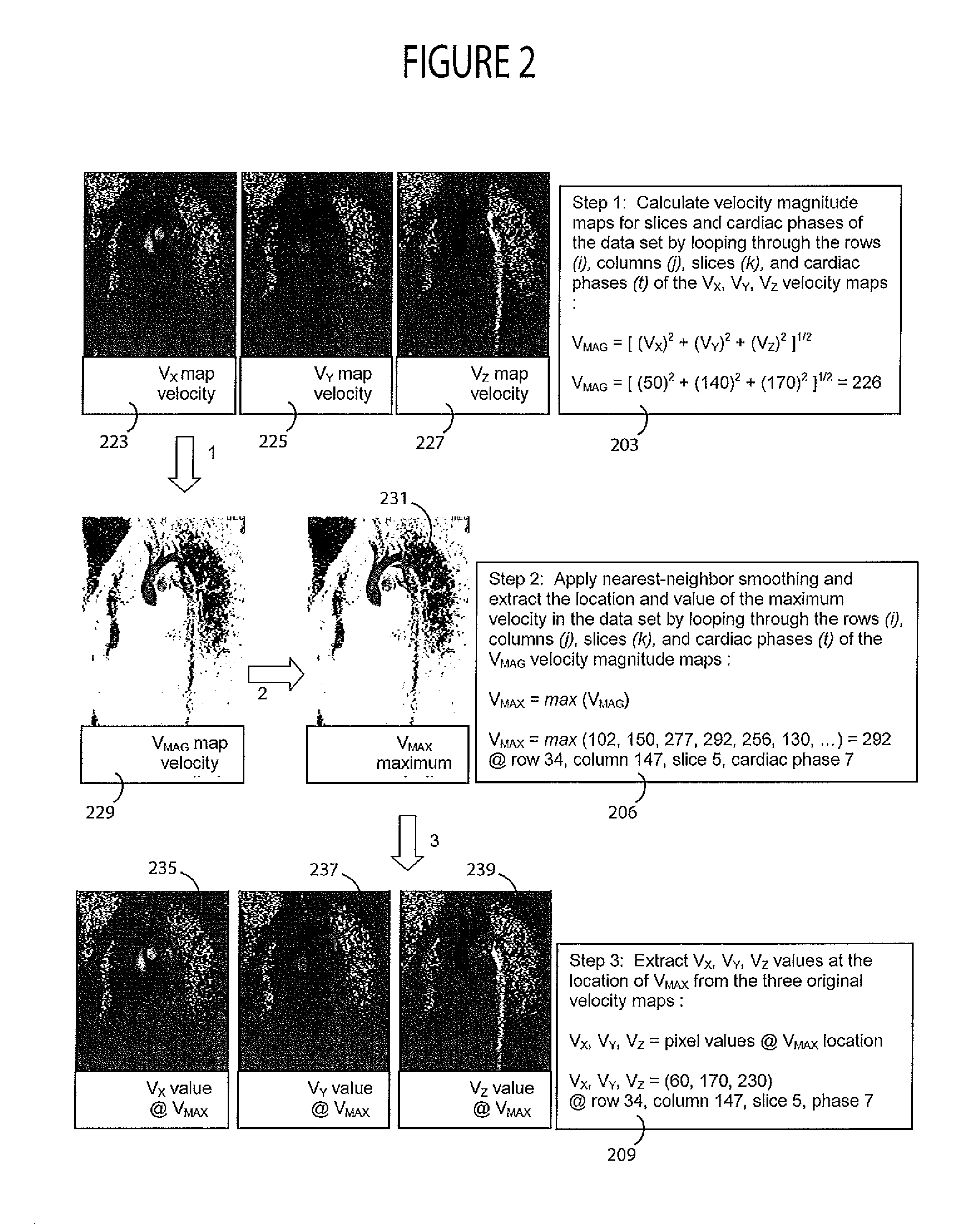
A system improves accuracy of blood flow peak velocity measurements as well as the speed and precision of an MR data acquisition workflow. A system for blood flow velocity determination in MR imaging comprises an MR imaging system. The MR imaging system acquires a three dimensional (3D) MR imaging dataset of a patient anatomical volume of interest and a one dimensional (1D) MR imaging dataset within the volume of interest automatically aligned in response to 3D vector directional information. An image data processor derives the 3D vector directional information by, deriving velocity magnitude data using the acquired 3D MR imaging dataset, identifying maximum velocity data using the derived velocity magnitude data and transforming the identified maximum velocity data to provide the 3D vector directional information. A calculation processor uses the acquired 1D MR imaging dataset to calculate a blood flow velocity in a direction determined by the 3D vector directional information.

Description

[0001]This is a non-provisional application of provisional application Ser. No. 61 / 295,865 filed 18 Jan., 2010, by G. McNeal et al.FIELD OF THE INVENTION[0002]This invention concerns a system for blood flow velocity determination in MR imaging, involving using a one dimensional (1D) MR imaging dataset and a three dimensional (3D) MR imaging dataset to calculate a blood flow velocity.BACKGROUND OF THE INVENTION[0003]Phase-contrast magnetic resonance image data acquisition with velocity-encoding provides cardiovascular flow visualization and quantification of severity of stenosis by evaluating a peak blood flow velocity within a core of a post-stenotic jet. However, this method often underestimates peak velocity of flow jets due in part to reliance on subjective alignment of a velocity-encoding axis employed by a pulse sequence used for MR data acquisition, with the principle axis of the jet, and also due in part to using insufficient temporal resolution when sampling blood flow data....

Claims


Application Information

Patent Timeline
IPC IPC(8): G01R33/48
CPCG01R33/56316
Inventor MCNEAL, GARYGLIELMI, CHRISTOPHERWEALE, PETER
Owner SIEMENS MEDICAL SOLUTIONS USA INC
Why Eureka
Try Eureka