Lens driving apparatus

a technology of driving apparatus and lens, which is applied in the direction of printers, instruments, cameras, etc., can solve the problems of difficult to realize a lens driving apparatus of small size and multifunctionality, and achieve the effect of reducing manufacturing costs, increasing accuracy of blurring control, and facilitating assembly

Active Publication Date: 2011-07-21
TDK TAIWAN
View PDF16 Cites 133 Cited by
  • Summary
  • Abstract
  • Description
  • Claims
  • Application Information

AI Technical Summary

Benefits of technology

[0043]Against this, in the present invention, it is not necessary to connect the betweenness of the movable portion and the fixed portion by FPC for transferring an image data by fixing the image sensor to the base portion (fixed portion). As a result, the movement of the lens portion which is movable portion to the fixed portion can be made smoothly as well as a noise signal generated by bending of the FPC and the like can be prevented so that the accuracy of blurring control can be increased. Also, by fixing the image sensor to the base portion (fixed portion), assembling the lens driving apparatus can become easier which contributes for reducing manufacturing cost.

Problems solved by technology

Therefore, in a conventional art, it has been difficult to realize a lens driving apparatus which is small size having multi functions.

Method used


Image

  • Lens driving apparatus
  • Lens driving apparatus
  • Lens driving apparatus

Examples


first embodiment

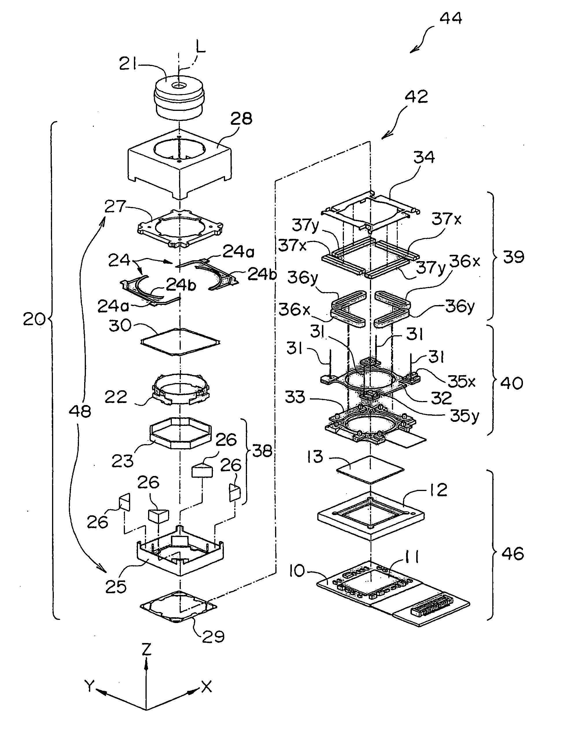
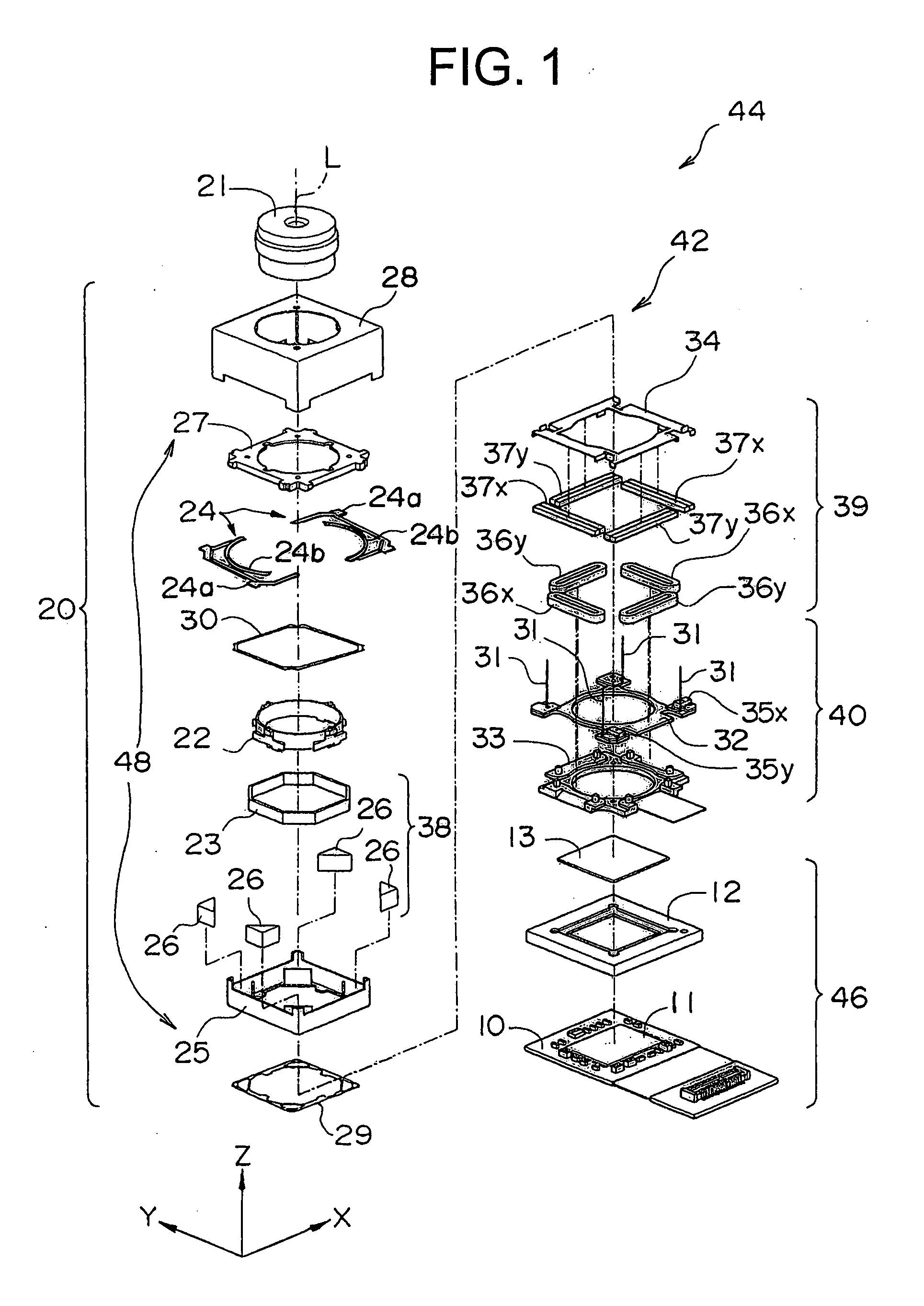
[0049]FIG. 1 is a disassembled perspective view of a camera unit 44 including a lens driving unit 42 according to one embodiment of the present invention. The camera unit 44 is configured by the lens driving unit 42 and an image taking element unit 46. Note that, in explanation of the camera unit 44, as shown in the coordinate described in FIG. 1 to FIG. 5, it will be specified that along a direction of a light axis of a lens portion 21 included in the lens driving unit 42, a direction from an image sensor 11 to the lens portion 21 is defined as a positive direction of Z-axis, vertical directions to a light axis L of the lens portion 21 are defined as X-axis direction and Y-axis direction. Note that, the X-axis, Y-axis and Z-axis are vertical each other.

[0050]The image taking element unit 46 comprises a filter 13, a bracket 12, an image sensor 11, an image sensor base plate 10 and the like. The image sensor 11 is composed of a solid image taking element such as CCD, CMOS and the lik...


PUM


Abstract

A lens driving apparatus comprises a lens portion having at least one lens (21), a first driving portion (39) to cause a movement of said lens portion relatively to a base portion (40) along a vertical direction of a light axis (L) of said lens portion, and a second driving portion (38) to cause a movement of said lens portion relatively to said base portion along said light axis.

Description

BACKGROUND OF THE INVENTION[0001]1. Field of the Invention[0002]The present invention relates to a lens driving apparatus used for, for example, a camera module of mobile phone and the like.[0003]2. Description of the Related Art[0004]For a lens driving apparatus preferably used for a camera module of a mobile phone and the like, it has been suggested that a lens holder is sandwiched by a pair of ring shaped springs which are arranged at an axis direction so as to perform focusing action and the like (refer to JP Patent Laid Open No. 2004-280031).[0005]In a lens driving apparatus according to a conventional art, a lens group supported by a lens holder can perform only focusing action, in order for giving other functions such as blurring compensation and the like to the lens driving apparatus, it was necessary to equip a lens group and the like for blurring compensation separately.[0006]Therefore, in a conventional art, it has been difficult to realize a lens driving apparatus which ...

Claims


Application Information

Patent Timeline
Patent Type & Authority Applications(United States)
IPC IPC(8): H04N5/225G02B7/04
CPCG02B7/08G03B3/10G02B27/646G02B7/04H02K41/0356H04N23/68
Inventor HU, CHAO-CHANGWU, FU-YUANCHAN, YI-LANG
Owner TDK TAIWAN
Why Eureka
Try Eureka