Base station antenna in a mobile communication system

Inactive Publication Date: 2011-07-21
KMW INC
View PDF14 Cites 5 Cited by
  • Summary
  • Abstract
  • Description
  • Claims
  • Application Information

AI Technical Summary

Benefits of technology

[0011]As is apparent from the above description, a BS antenna for a mobile communication system according to the present invention has the following effects. Firstly, since amplifiers are distributed and directly connected to radiation elements, an NF that might be degraded by a feeding circuit within an antenna can be minimized. The resulting improved uplink throughput decreases a retransmission rate, thereby improving downlink throughput. Because a received signal is amplified separately in a plurality of amplifiers, a rapid drop in reception level is prevented in spite of an error in any of the amplifiers. Secondly

Problems solved by technology

The long signal transmission line between the BTS and the antenna causes a great signal loss during transmission of a transmission signal and a reception signal via the feeder cable.
The signal loss leads to coverage reduction caused by decreased transmit power and the decrease of reception sensitivity caused by a poor reception Noise Figure (NF).
The above

Method used


Image

  • Base station antenna in a mobile communication system
  • Base station antenna in a mobile communication system
  • Base station antenna in a mobile communication system

Examples


Example

[0036]Throughout the drawings, the same drawing reference numerals will be understood to refer to the same elements, features and structures.

MODE FOR THE INVENTION

[0037]The matters defined in the description such as a detailed construction and elements are provided to assist in a comprehensive understanding of exemplary embodiments of the invention. Accordingly, those of ordinary skill in the art will recognize that various changes and modifications of the embodiments described herein can be made without departing from the scope and spirit of the invention. Also, descriptions of well-known functions and constructions are omitted for clarity and conciseness.

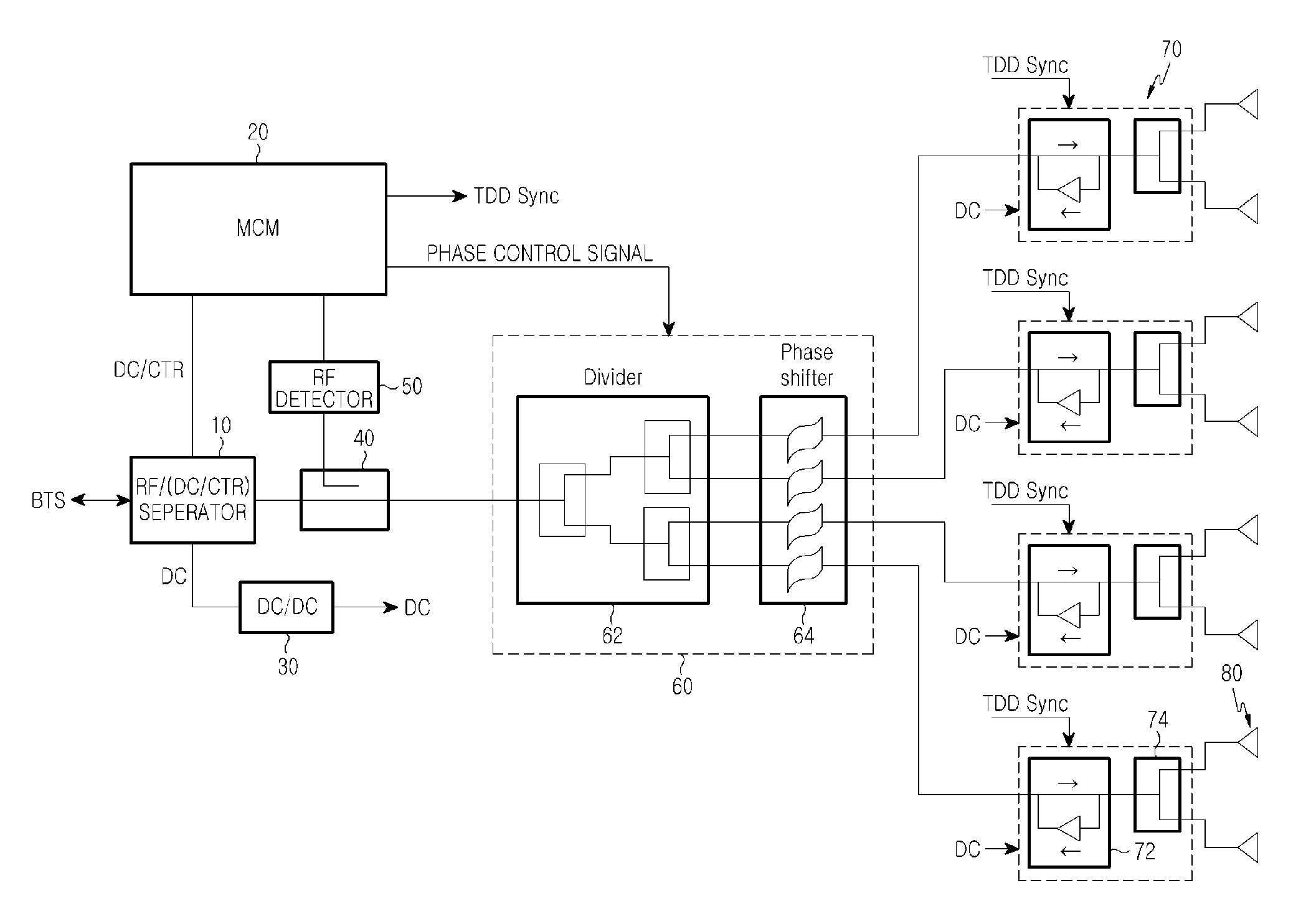
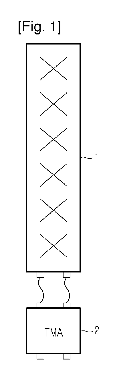
[0038]FIG. 2 is an overall block diagram of a Base Station (BS) antenna in a Time Division Duplex (TDD) mobile communication system according to an exemplary embodiment of the present invention.

[0039]Referring to FIG. 2, the BS antenna of the present invention is basically configured so as to be connected directly to a Base Transc...


PUM


Abstract

A Base Station (BS) antenna in a mobile communication system is provided, in which a reflective plate has a frontal surface onto which radiation elements are attached, and at least one protector is attached onto the reflective plate, surrounding at least part of the reflective plate.

Description

TECHNICAL FIELD[0001]The present invention relates to a Base Station (BS) antenna in a mobile communication system.BACKGROUND ART[0002]Generally, in a mobile communication BS system, a BS amplifies a transmission signal through a high-power amplifier, transmits the amplified signal to an antenna via a feeder cable, and radiates the signal through the antenna. The antenna receives a signal and transmits the received signal to a Low Noise Amplifier (LNA) in the BS through the feeder cable. The LNA amplifies a weak received signal. For the purpose of providing a service, the antenna is mounted on a high place such as a rooftop or a tower and a Base Transceiver Station (BTS) is installed within a building or under a tower. Hence, a long transmission line is established between the BTS and the antenna.[0003]The long signal transmission line between the BTS and the antenna causes a great signal loss during transmission of a transmission signal and a reception signal via the feeder cable. ...

Claims


Application Information

Patent Timeline
IPC IPC(8): H04W4/00H04J1/00H01Q1/42H01Q19/10H01Q23/00H04B1/3822H04B1/40
CPCH01Q1/246H01Q3/26H01Q3/24H01Q3/04F21S2/005F21V17/12F21V21/002F21V21/005F21Y2115/10Y10S362/80
Inventor KIM, DUK-YONGKIM, IN-HOLEE, KANG-HYUNCHOI, OH-SEOGSUNG, SEOKLEE, JUNG-PILMOON, YOUNG-CHANKIM, TAEK-DONG
Owner KMW INC
Why Eureka
Try Eureka