Methods for determining fractional flow reserve

a fractional flow and flow reserve technology, applied in the field of methods for determining fractional flow reserve, can solve the problems of inability to reliably accurately determine the functional significance of intermediate coronary lesions, and the lack of correlation between the angiographic delineated stenosis and the severity of the physiologic condition, and achieve the effect of reliably accurate determination

Active Publication Date: 2011-07-21
3DT HLDG
View PDF8 Cites 81 Cited by
  • Summary
  • Abstract
  • Description
  • Claims
  • Application Information

AI Technical Summary

Benefits of technology

[0018]In at least one embodiment of a device for determining fractional flow reserve of a fluid within a luminal organ of the present disclosure, the device comprises an elogated body sized and shaped to fit within a luminal organ, at least one pair of excitation electrodes positioned along the elongated body, and at least two pairs of detection electrodes positioned along the elongated body between the at least one pair of excitation electrodes, wherein the at least two pairs of detection electrodes are positioned a predetermined distance from each other, wherein when the device is positioned within the luminal organ, the device is operable to detect a first conductance of a first fluid having a first conductivity within the luminal organ using the at least two pairs of detection electrodes, the device further operable to detect a second conductance of a second fluid having a second conductivity using the at least two pairs of detection electrodes upon introduction of the second fluid within the luminal organ at or near the at least two pairs of detection electrodes. In at least one embodiment, the second fluid detected by using the at least two pairs of detection electrodes allows for the determination of flow velocity based upon timing of the detected second fluid by using the at least two pairs of detection electrodes and the distance between the at least two pairs of detection electrodes.
[0021]In at least one embodiment of a system for determining fractional flow reserve of a fluid within a luminal organ of the present disclosure, the data acquisition and processing system is further operable to determine fractional flow reserve when the device is positioned within the luminal organ at or near a stenosis, wherein the fractional flow reserve is based upon the flow velocity, a mean aortic pressure within the luminal organ, and at least one cross-sectional area at or near the stenosis. In another embodiment, the flow velocity allows for the determination of volumetric flow based upon the flow velocity and a cross-sectional area of the luminal organ.

Problems solved by technology

Although the current “gold standard” for assessing coronary artery disease (CAD) is angiography, it has serious limitations in evaluating the functional significance of intermediate coronary lesions (comprising 30-70% stenosis).
Moreover, studies have shown a lack of correlation between the angiographic delineated stenosis with their physiologic severity on coronary flow.
Since this condition is very difficult to meet in clinical practice as the tip of the wire is difficult to align with the direction of flow, the measurements are not reliably accurate and this method has not enjoyed clinical utility.
In summary, there are well-known limitations to the use of visual estimation to assess the severity of coronary artery disease and luminal stenosis.
This is especially true in the case of intermediate coronary lesion where coronary angiography is very limited in distinguishing ischemia-producing intermediate coronary lesions from non-ischemia-producing ones.
Previous devices involving Doppler flow wires also have serious limitations as referenced above.

Method used


Image

  • Methods for determining fractional flow reserve
  • Methods for determining fractional flow reserve
  • Methods for determining fractional flow reserve

Examples


Embodiment Construction

[0036]For the purposes of promoting an understanding of the principles of the present disclosure, reference will now be made to the embodiments illustrated in the drawings, and specific language will be used to describe the same. It will nevertheless be understood that no limitation of the scope of this disclosure is thereby intended.

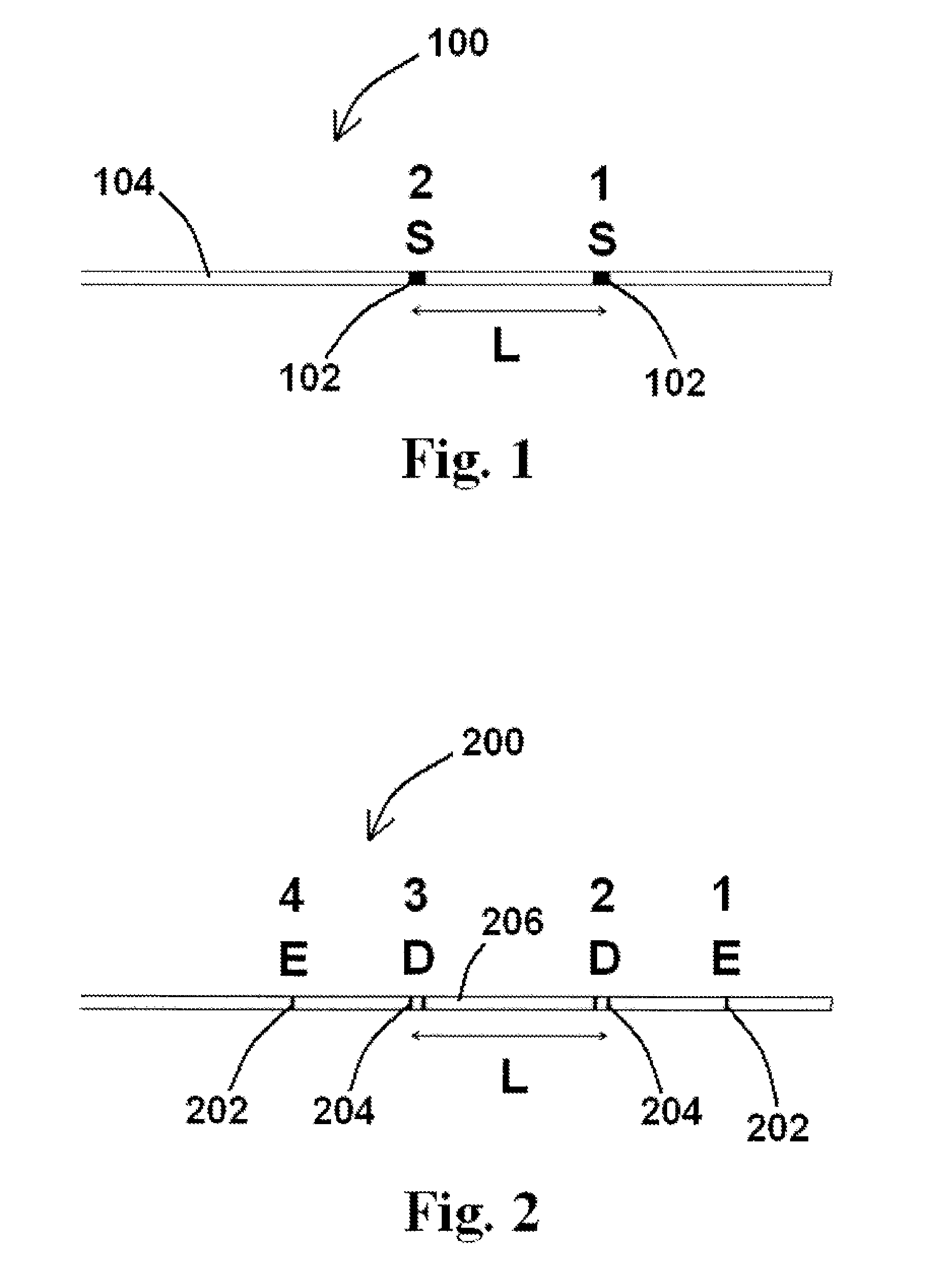
[0037]The disclosure of the present application provides devices, systems, and methods for determining fractional flow reserve (FFR), including devices, systems, and methods for determining FFR using impedance. An exemplary method for performing the same would utilize one or more devices (or elements / features of such a device) operable to detect a change in at least one characteristic within a vessel flow based upon the introduction of a change to the initial flow. Such methods, and devices and systems for performing such methods, are useful for the diagnosis of disease (including CAD) by providing accurate values for flow velocity, whereby changes in f...


PUM


Abstract

Devices, systems, and methods for determining fractional flow reserve. At least one method for determining fractional flow reserve of the present disclosure comprises the steps positioning a device comprising at least two sensors within a luminal organ at or near a stenosis, wherein the at least two sensors are separated a predetermined distance from one another, operating the device to determine flow velocity of a second fluid introduced into me luminal organ to temporarily displace a first fluid present within the luminal organ, and determining fractional flow reserve at or near the stenosis based upon the flow velocity, a mean aortic pressure within the luminal organ, and at least one cross-sectional area at or near the stenosis. Devices and systems useful for performing such exemplary methods are also disclosed herein.

Description

PRIORITY[0001]The present application is related to and claims the benefit of U.S. Provisional Patent Application Ser. No. 61 / 098,837, filed Sep. 22, 2008, the contents of which are incorporated herein by reference in its entirety.BACKGROUND[0002]Coronary heart disease remains the leading cause of morbidity and mortality in the United States and the developed world. Although the current “gold standard” for assessing coronary artery disease (CAD) is angiography, it has serious limitations in evaluating the functional significance of intermediate coronary lesions (comprising 30-70% stenosis). Coronary angiography relies on a visual interpretation of coronary anatomy. A number of studies have documented the large intra- and inter-observer variability that results from visual grading of coronary stenotic lesions. Moreover, studies have shown a lack of correlation between the angiographic delineated stenosis with their physiologic severity on coronary flow. This stems from the highly non...

Claims


Application Information

Patent Timeline
Patent Type & Authority Applications(United States)
IPC IPC(8): A61B5/0215A61B5/026A61B5/296
CPCA61B5/026A61B5/0275A61B5/053A61B5/02158A61B5/02007A61B5/028A61B5/0295A61B5/6852
Inventor KASSAB, GHASSAN S.
Owner 3DT HLDG
Why Eureka
Try Eureka