Plasma method for disposing of waste material, and apparatus therefor

a technology of waste material and plasma, which is applied in the direction of coking carbonaceous materials, special form destructive distillation, combustion process, etc., can solve the problems of high vacuum, furnace description, and not being well suited to steady feeding of solid waste material, etc., and achieves the effect of reducing energy costs

Inactive Publication Date: 2011-07-28
RE 2
View PDF7 Cites 5 Cited by
  • Summary
  • Abstract
  • Description
  • Claims
  • Application Information

AI Technical Summary

Benefits of technology

[0015]It is therefore a feature of the present invention to provide a method and an apparatus for treating a w

Problems solved by technology

A vacuum higher than what is required to this purpose could not be used in the equipment according to the above mentioned application, as confirmed by the square cross section of the furnace, which is not adapted to work in deep vacuum conditions.
Furthermore, the furnace described in WO2004/087840 is not well suited for being steadily fed with solid waste material, without appreciable vacuum loss and/or appreciable air inlet.
In fact, the feeding duct is just equipped with a “isolation valve”, i.e. an on-off valve, which cannot ensure a gas-tight seal.
Similarly, it is qu

Method used


Image

  • Plasma method for disposing of waste material, and apparatus therefor
  • Plasma method for disposing of waste material, and apparatus therefor
  • Plasma method for disposing of waste material, and apparatus therefor

Examples


Embodiment Construction

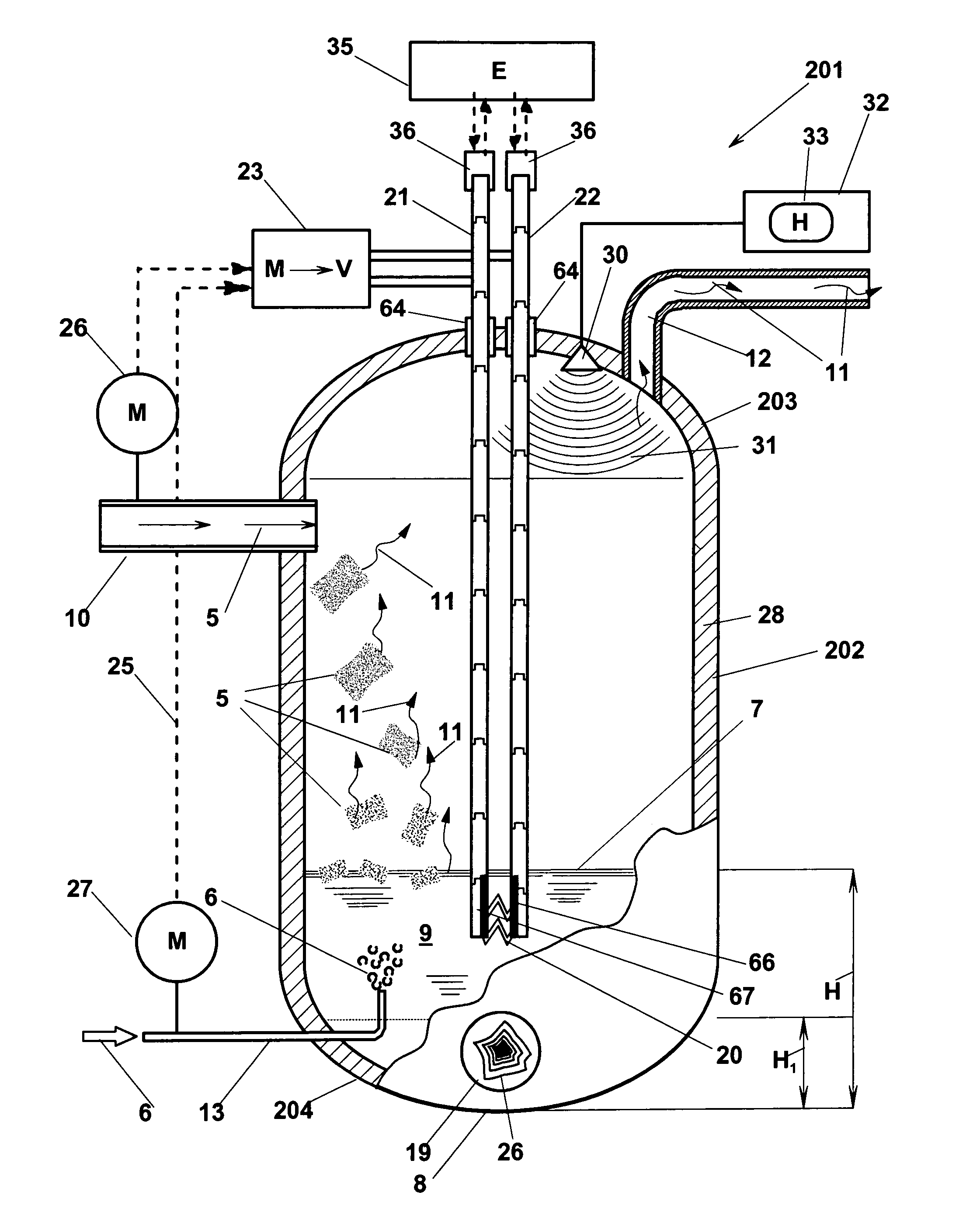
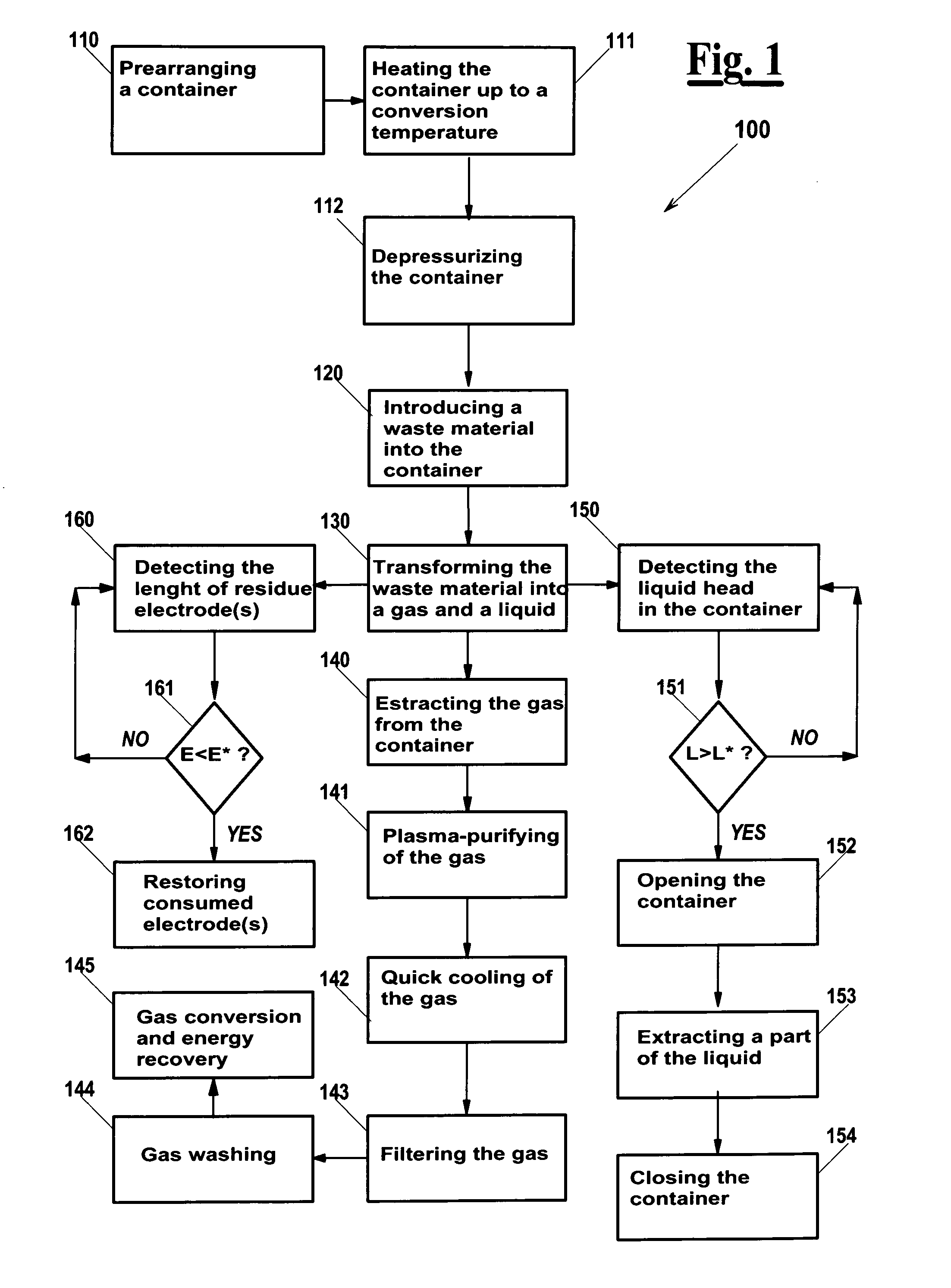
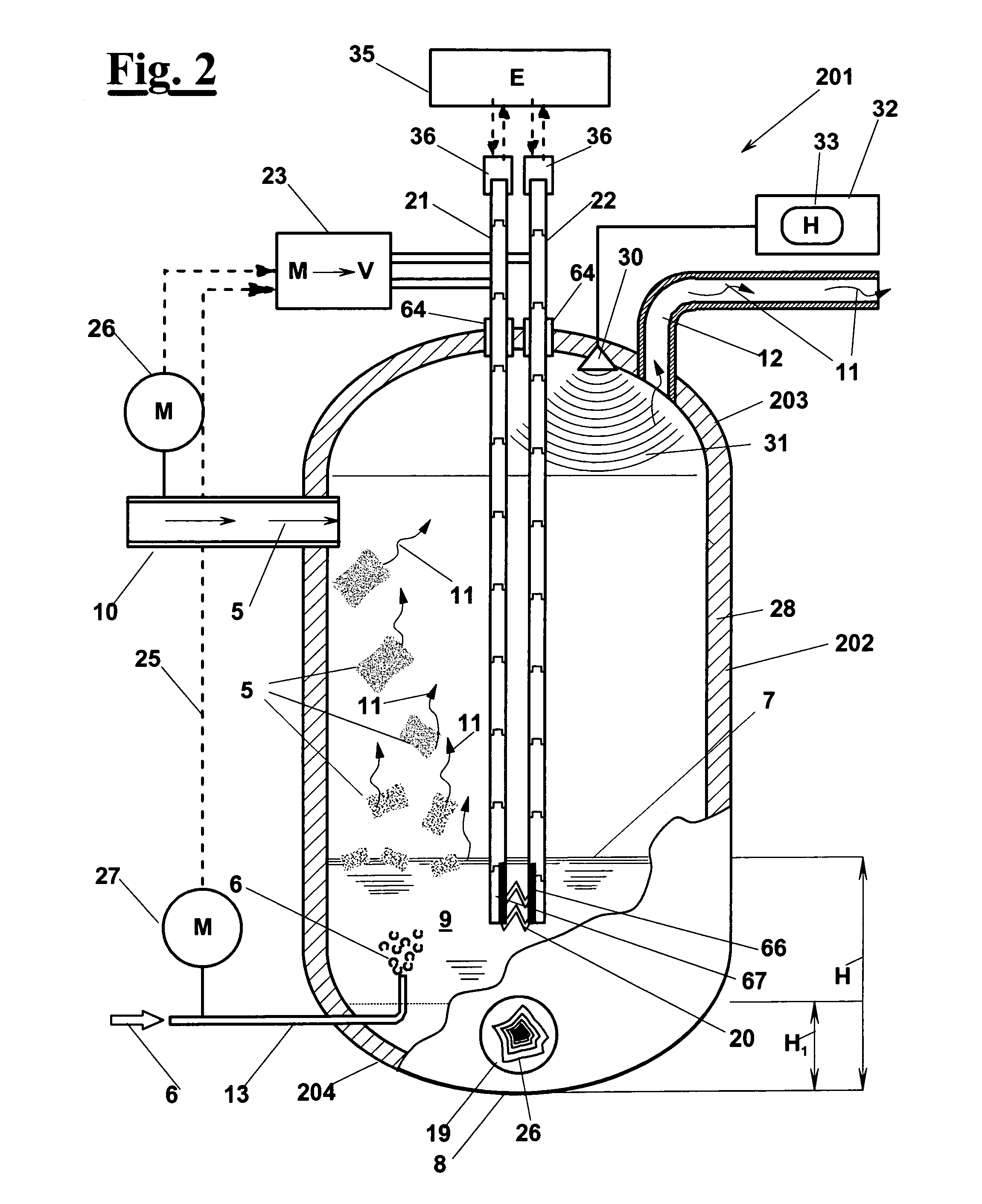
[0091]With reference to the flow diagram of FIG. 1, a method 100 is described for transforming a waste material, according to the invention. Method 100 comprises a step 110 of prearranging a vessel, a step 111 of heating the vessel up to a conversion temperature, which is normally set between 1600 and 2000° C., as well as a step 112 of depressurizing the vessel to an absolute pressure, which is preferably set between 1 and 10 millibar, and most preferably about 4 millibar. Depressurizing step 112 is followed by a step 120 of introducing the waste material into the vessel; step 120 is carried out in such a way that air is prevented from entering into the vessel together with the waste material, which would cause vacuum loss and combustion of a part of the waste material. The conversion temperature is high enough to cause and maintain a transformation step 130 of the waste material into two fractions, a ionic gas 11, i.e. a plasma, and a substantially liquid fraction 9 that is accumul...


PUM


Abstract

A method and an apparatus based on a reactor vessel (201) that is brought to a predetermined vacuum degree, in particular said vacuum degree set between 2 and 6 absolute millibar, an to a high temperature. A waste material is continuously introduced in the vessel (202), in particular a solid waste material (5) is introduced in such a way that a vacuum loss from the vessel (201) is prevented. Owing to the high temperature, waste material (5) forms a plasma that undergoes a molecular rearrangement, which gives origin to a substantially liquid residue that is collected in a bottom portion (204) of reactor (201), and to a gas (11). The gas (11), which mainly comprises carbon monoxide, hydrogen, carbon dioxide and steam, i.e. a typical syngas composition, is continuously taken away from the vessel (201) through a duct (12), and is sent to subsequent treatments to obtain a gas fuel that can be burnt by devices such as a gas turbine, a motor or a boiler. The high temperature in reactor (201) is maintained due to a current in the form of electric discharges (20) that is established between two electrodes (21,22) below the liquid head (7). The substantially liquid residue is periodically discharged to maintain a liquid head height (7) not exceeding a reference height value H*, in such a way that air inlet into vacuum loss from the vessel (201) is prevented.

Description

FIELD OF THE INVENTION[0001]The present invention relates to a method for disposing of a waste material, which provides a transformation of the waste into a plasma. The invention also refers to an apparatus for carrying out the method.[0002]The method and the apparatus are well suited for treating a solid, liquid or gas waste material, which may contain an organic and an inorganic part. In particular, the waste material may be a municipal waste, a hospital or surgery waste, a harmful or infected waste, a wastewater sludge, a metal workshop waste, a slaughterhouse waste, a farm waste, a ground tires, etc.BACKGROUND OF THE INVENTION[0003]The need is felt of waste disposal techniques, which overcome the well known drawbacks of traditional techniques, like landfill and incineration, and possibly allow recovering energy.[0004]In particular, methods are known that provide heating a waste material up to a temperature at which the organic part of the waste material turns into a ionized gas,...

Claims


Application Information

Patent Timeline
IPC IPC(8): C10B53/00C10B7/00C10B31/00
CPCB09B3/00B09C1/06F23G5/085F23J1/00F23G5/448F23G2205/121F23G2205/18F23G5/444
Inventor FABBRI, MARIOSONNO, ENRICO
Owner RE 2
Why Eureka
Try Eureka