Slant-truss crane rail

a crane rail and truss technology, applied in the direction of trolley cranes, runways, braking devices for hoisting equipment, etc., can solve the problems of reducing the overall mass of the bridge, reducing the momentum associated with the bridge, and increasing the control of the operator, so as to reduce the overall mass of the one or more bridge rails, reduce the mass of the bridge, and facilitate the movement of a load

Active Publication Date: 2011-07-28
GIVENS RAY
View PDF30 Cites 18 Cited by
  • Summary
  • Abstract
  • Description
  • Claims
  • Application Information

AI Technical Summary

Benefits of technology

[0008]In a first aspect, the invention is directed to an overhead crane with one or more bridge rails, that incorporates a reinforcement truss into its one or more bridge rails so as to reduce the overall mass of the one or more bridge rails. This facilitates movement of a load carried by the bridge by an operator to a destination point, particularly in embodiments wherein the one or more bridge rails do not have any bridge drive motors thereon. Reducing the mass of the bridge can increase the amount of lifted load that can comfortably be maneuvered by an operator, particularly when the bridge is manually moved along the runway. Additionally, reducing the mass of the bridge reduces the momentum associated with the bridge, which can increase the amount of control that the operator has when it is desired to stop the bridge when the load has been maneuvered to its desired destination point. The second reinforcement members may have first and second ends that are inserted into receiving apertures in the first reinforcement member and in a bracket that mounts to the bridge rail respectively. In embodiments wherein the bridge includes two rails and is capable of supporting a load in such a way as to generate a downward force that is offset from the bridge axis, the second reinforcement members may be connected to the first reinforcement member and to brackets in such a way as to prevent the withdrawal of the second reinforcement members from the receiving apertures.
[0009]In another aspect, the invention is directed to a retrofit kit that permits the reinforcing structure described above to be easily retrofitted to existing bridge rails without the need for welding and without the need to install an inordinate quantity of fasteners.

Problems solved by technology

Additionally, reducing the mass of the bridge reduces the momentum associated with the bridge, which can increase the amount of control that the operator has when it is desired to stop the bridge when the load has been maneuvered to its desired destination point.

Method used


Image

  • Slant-truss crane rail
  • Slant-truss crane rail
  • Slant-truss crane rail

Examples


Embodiment Construction

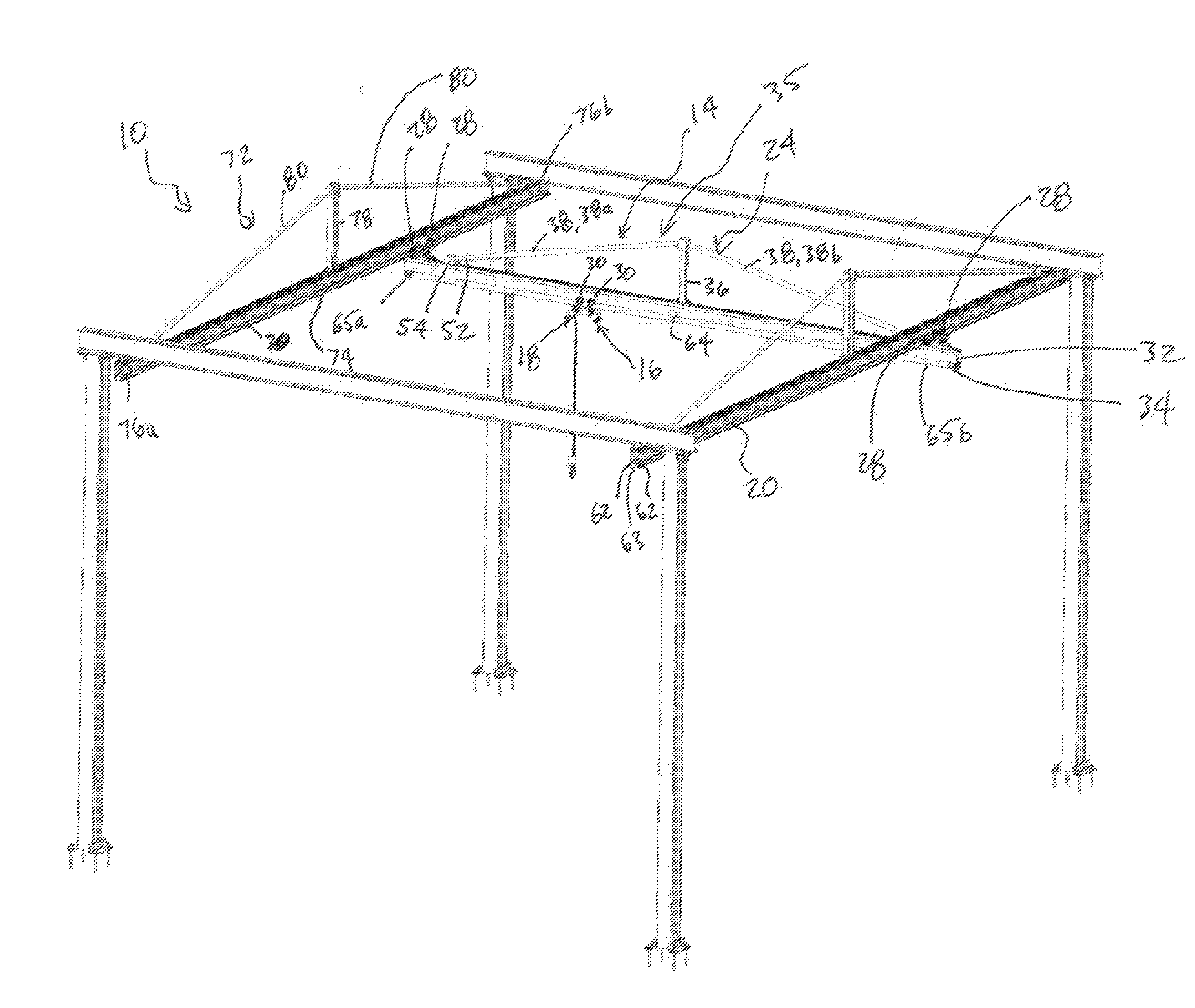
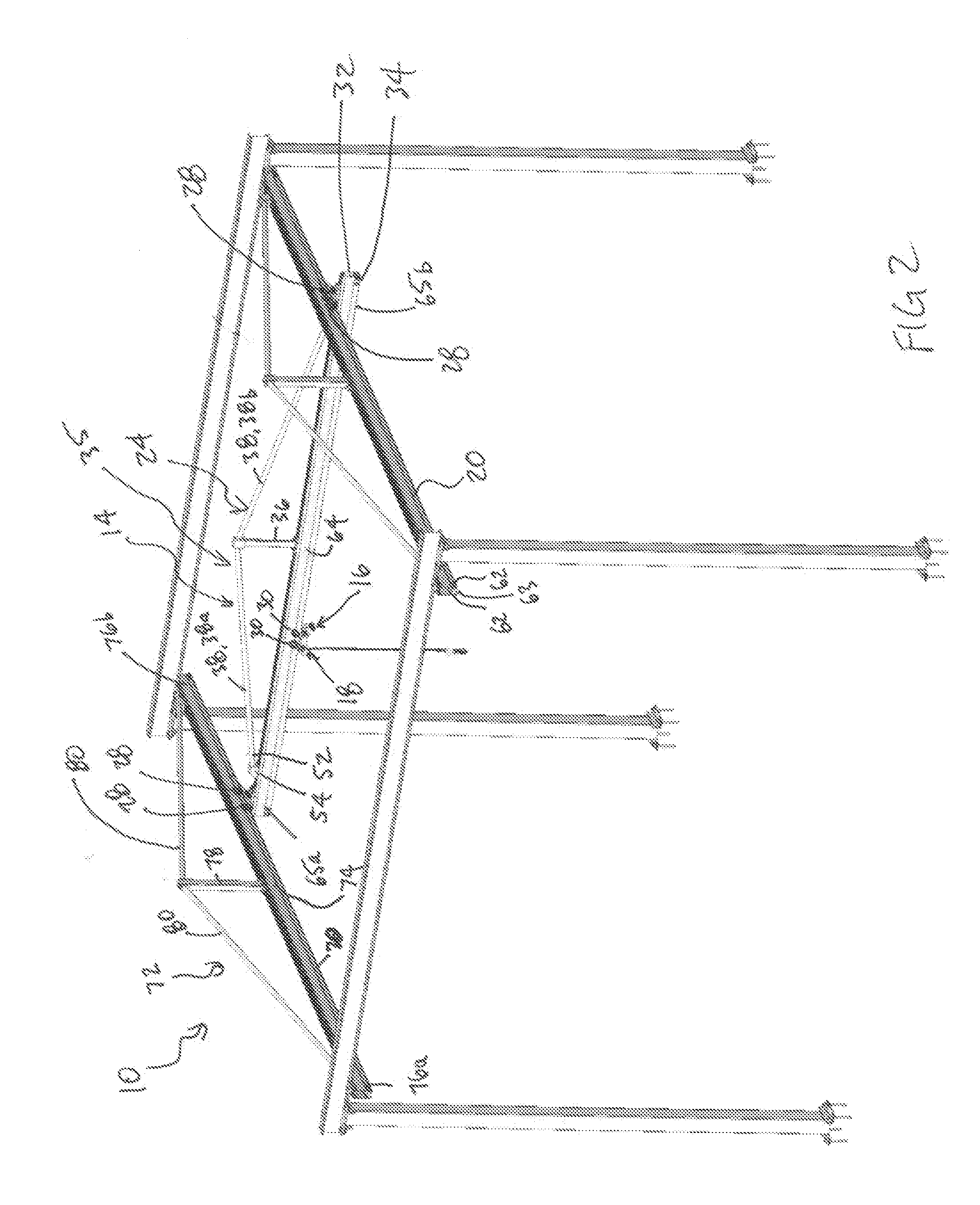
[0028]Reference is made to FIG. 2, which shows an overhead crane 10 in accordance with an embodiment of the present invention. The overhead crane 10 includes a pair of runway rails 20, a bridge 14, a trolley 16 and a lifting device 18, such as a hoist. The runway rails 20 extend parallel to a generally horizontal runway axis. The bridge 14 is made up of a single bridge rail 24 that extends parallel along a generally horizontal bridge axis that is perpendicular to the runway axis. The bridge rail 24 is rollably supported on the runway rails 20 at each end by bridge wheels 28. The bridge 14 may be manually rollable along the runway rails 20 through the bridge wheels 28. Alternatively a bridge drive motor may be provided (not shown) to drive the bridge 14 on the runway rails 20. The trolley 16 is rollably supported on the bridge rail 24 by means of trolley wheels 30. The trolley 16 may be manually rollable along the bridge rail 24. Alternatively a trolley drive motor (not shown) may be...


PUM


Abstract

In one aspect, the invention is directed to an overhead crane with one or more bridge rails, that incorporates a reinforcement truss into its one or more bridge rails so as to reduce the overall mass of the one or more bridge rails. This facilitates movement of a load carried by the bridge by an operator to a destination point, particularly in embodiments wherein the one or more bridge rails do not have any bridge drive motors thereon. Reducing the mass of the bridge can increase the amount of lifted load that can comfortably be maneuvered by an operator, particularly when the bridge is manually moved along the runway. Additionally, reducing the mass of the bridge reduces the momentum associated with the bridge, which can increase the amount of control that the operator has when it is desired to stop the bridge when the load has been maneuvered to its desired destination point. The second reinforcement members may have first and second ends that are inserted into receiving apertures in the first reinforcement member and in a bracket that mounts to the bridge rail respectively. In embodiments wherein the bridge includes two rails and is capable of supporting a load in such a way as to generate a downward force that is offset from the bridge axis, the second reinforcement members may be connected to the first reinforcement member and to brackets in such a way as to prevent the withdrawal of the second reinforcement members from the receiving apertures.

Description

FIELD OF THE INVENTION[0001]The present invention relates to overhead cranes for use in industrial plants, and more particularly to an overhead crane that is configured to lift a load using motorized means, but wherein an operator manually pulls or pushes the lifted load to its destination.BACKGROUND OF THE INVENTION[0002]Overhead cranes typically include a pair of runways, which may be mounted fixedly to the roof joists of an industrial plant, a bridge that includes one or more bridge rails which have rollers at their ends for rolling along the runway rails, and a trolley which has rollers thereon for rolling along the one or more bridge rails. A hoist or some other lifting device is provided on the trolley for lifting a load.[0003]For cranes having capacities of more than 4000 lb, I-Beam crane rails are typically used for the one or more bridge rails and for the runways. For cranes having capacities of less 4000 lb, enclosed track crane rails, such as the crane rail shown at 100 i...

Claims


Application Information

Patent Timeline
Patent Type & Authority Applications(United States)
IPC IPC(8): B66C17/00
CPCB66C5/02B66C7/04B66C7/02B66C5/10
Inventor GIVENS, RAY
Owner GIVENS RAY
Why Eureka
Try Eureka