Light fixture with an electrodeless plasma source

a technology of electrodeless plasma and light fixture, which is applied in lighting and heating apparatus, lighting heating/cooling arrangements, color televisions, etc., can solve the problems of flickering of elsps bulbs, changing optical spectrum, and color temperature of elsps light tending to dri

Active Publication Date: 2011-07-28
MARTIN PROFESSIONAL
View PDF14 Cites 5 Cited by
  • Summary
  • Abstract
  • Description
  • Claims
  • Application Information

AI Technical Summary

Benefits of technology

[0006]It is hereby achieved that the electromagnetic radiation used to excite the gas-fill that escapes the ELSPS resonator can be absorbed and grounded by the metal grid and the light fixture can thus be used in entertainment lighting, conventional lighting and / or video projectors without causing electromagnetic interference with the surroundings. The skilled person realizes that the metal grid can be designed in many different ways as the main purpose of the metal grid is to absorb and ground electromagnetic radiation emitted by the resonator. The metal grid can e.g. be embodied as metal screens, metal coatings or a lattice of metal wires / bars.
[0014]The light path in the light fixture can be folded at least once, which light path starting at the light source and passing through internal optical components, which light path is leaving the light fixture through the front lens, in which light fixture the light path is folded by at least one optical reflector. By folding the light path a much shorter projector or light fixture can be achieved. A further bonus by using the ELPS bulb in the folded projector or light fixture is achieved in that high frequency radiation generated at the ELPS is transmitted in the same direction as the light. By performing a folding by an optical reflector, this reflector can be made in a way in which there a no reflections of the electromagnetic energy.

Problems solved by technology

Some of the electromagnetic radiation used to excite the gas-fill, escapes the resonator which in many cases is unwanted electromagnetic interference with the surroundings.
Another issue is the fact that the ELPS bulb tends to flicker and changes it optical spectrum if not cooled properly.
Yet another issue is the fact that the color temperature of the light from the ELSP tends to drift when the ELSP is dimmed.
The ELPS is as a consequence very difficult to integrate in to complex optical systems like the ones used in entertainment lighting, such as moving heads and scanners, and in video projection systems.

Method used


Image

  • Light fixture with an electrodeless plasma source
  • Light fixture with an electrodeless plasma source
  • Light fixture with an electrodeless plasma source

Examples


Embodiment Construction

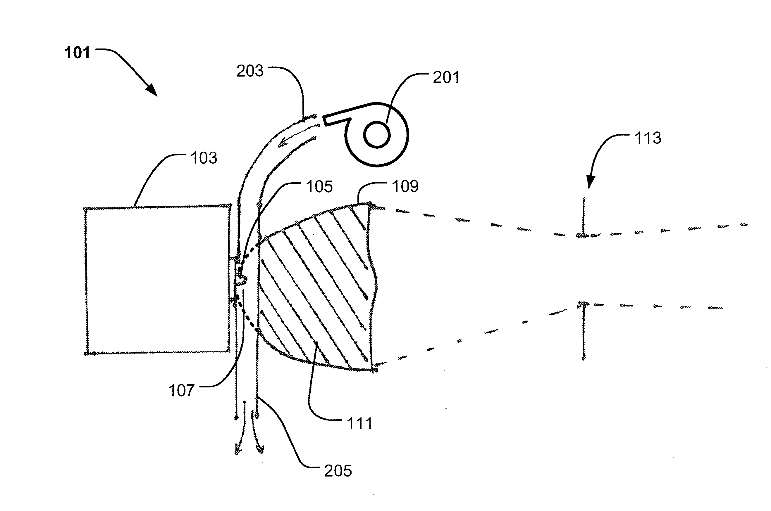
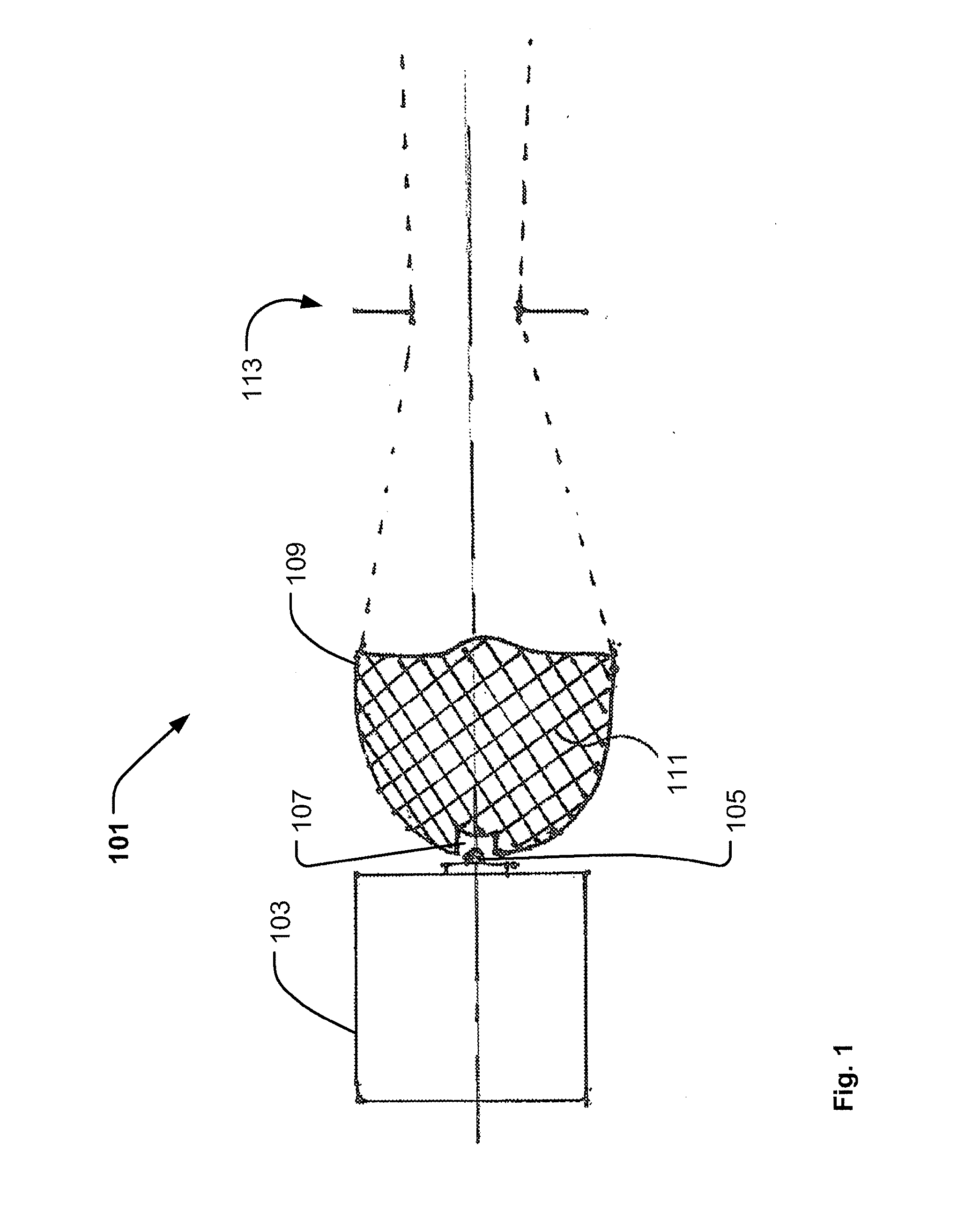
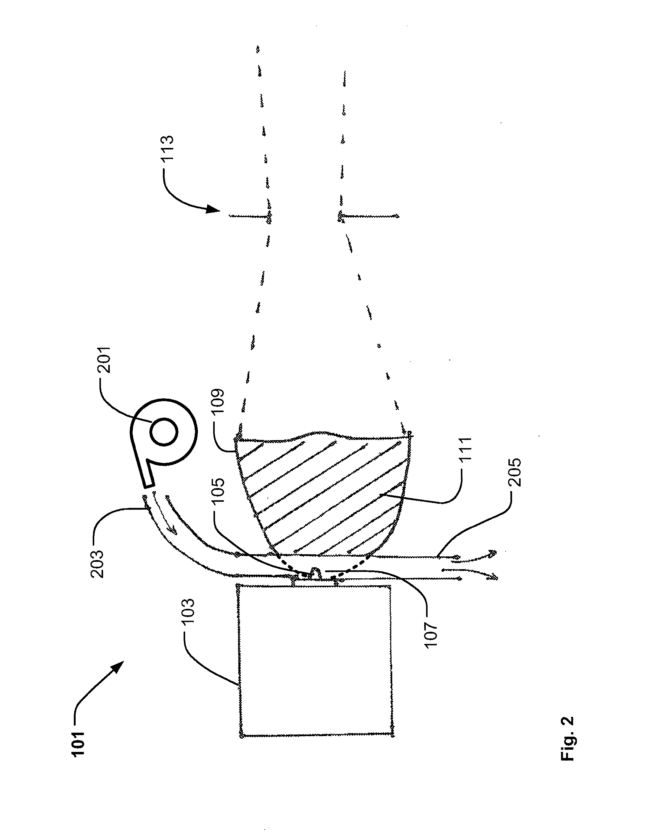
[0005]The scope of the present invention is to solve the above described problems and can be fulfilled by the preamble to claim 1 if the TIR lens comprises a metal grid covering at least a part of the TIR lens and where the metal grid is grounding electromagnetic radiation generated by said electrodeless plasma source.

[0006]It is hereby achieved that the electromagnetic radiation used to excite the gas-fill that escapes the ELSPS resonator can be absorbed and grounded by the metal grid and the light fixture can thus be used in entertainment lighting, conventional lighting and / or video projectors without causing electromagnetic interference with the surroundings. The skilled person realizes that the metal grid can be designed in many different ways as the main purpose of the metal grid is to absorb and ground electromagnetic radiation emitted by the resonator. The metal grid can e.g. be embodied as metal screens, metal coatings or a lattice of metal wires / bars.

[0007]The metal grid co...


PUM


Abstract

The present invention relates to a light fixture comprising an electrodeless plasma source, said electrodeless plasma source comprises a resonator and a light bulb, said light bulb is operating inside a cavity of a TIR where the TIR lens comprises a metal grid covering at least a part of said TIR lens, the metal grid grounding electromagnetic radiation generated by said electrodeless plasma source. In another embodiment, the light fixture comprises blowing means sending an air stream into the cavity. A further embodiment also comprises at least one LED, which ELPS bulb and the LED are controlled by a control system, which control system performs dimmer control of at least the ELPS and the LED.

Description

FIELD OF THE INVENTION[0001]The present invention relates to a light fixture with an electrodeless plasma source and to moving heads and video projectors having such light fixture.BACKGROUND OF THE INVENTION[0002]U.S. Pat. No. 6,737,809 concerns a dielectric waveguide integrated plasma lamp (DWIPL) with a body consisting essentially of at least one dielectric material having a dielectric constant greater than approximately 2, and having a shape and dimensions such that the body resonates in at least one resonant mode when microwave energy of an appropriate frequency is coupled into the body. A bulb positioned in a cavity within the body contains a gas-fill which when receiving energy from the resonating body fauns a light-emitting plasma.[0003]WO 2007 / 079496 concerns an electrode less plasma lamp comprising a lamp body including a solid dielectric material. The lamp includes a bulb received at least partially within an opening in the solid dielectric material and a radio frequency (...

Claims


Application Information

Patent Timeline
Patent Type & Authority Applications(United States)
IPC IPC(8): H05B35/00F21V7/00
CPCF21V7/0091F21V29/02H04N9/315H04N9/3144H01J65/044F21V29/67
Inventor JORGENSEN, DENNIS THYKJAER
Owner MARTIN PROFESSIONAL
Why Eureka
Try Eureka