Charger

a charging device and charging device technology, applied in the direction of electric vehicles, battery/fuel cell control arrangements, transportation and packaging, etc., can solve the problems of not being able to drive the 3-phase motor any more, taking a lot of time and labor to design an electric vehicle, etc., to simplify the connection of the communication line, simplify the circuit construction, and simplify the effect of the high-voltage battery charg

Inactive Publication Date: 2011-07-28
LS IND SYETEMS CO LTD
View PDF11 Cites 18 Cited by
  • Summary
  • Abstract
  • Description
  • Claims
  • Application Information

AI Technical Summary

Benefits of technology

[0034]According to the present disclosure, it is possible to simplify a construction of circuit by adding a buck-type single-phase motor and operating it in the buck-boost manner using a Y-connected 3-phase motor and an inverter, and to simply design an electric vehicle compared with a conventional technology in which an electric vehicle is designed to separately mount an inverter, a high-voltage charger and a low-voltage charger thereon.
[0035]Further, according to the present disclosure, it is possible to simplify a communication line connected outside since control can be made with one DSP.
[0036]Further, according to the present disclosure, it is possible to charge a low-voltage battery using power charged in a high-voltage battery as well as to charge the high-voltage battery with ease using a 3-phase motor and an inverter.

Problems solved by technology

However, the method has a limit to drive the 3-pahse motor with the charged power of the high-voltage battery, that is, it is not possible to drive the 3-phase motor any more when the power charged in the high-voltage battery is discharged more than a predetermined power level.
However, since the inverter, high-voltage charger and low-voltage charger are included separately with one another, it takes much time and labor to design an electric vehicle having each of the inverter, high-voltage charger and low-voltage charger mounted thereon.

Method used


Image

  • Charger
  • Charger
  • Charger

Examples


Embodiment Construction

[0044]Hereinafter, a detailed description is nothing but an example and an embodiment of the present disclosure. Further, principle and concept of the present disclosure are provided for the purpose of describing the present disclosure in the most usefully and easily.

[0045]Accordingly, while an unnecessarily-detailed construction beyond a basic understanding of the present disclosure is not provided, various forms with which those skilled in the art can implement in the substance of the present disclosure are exemplified through drawings.

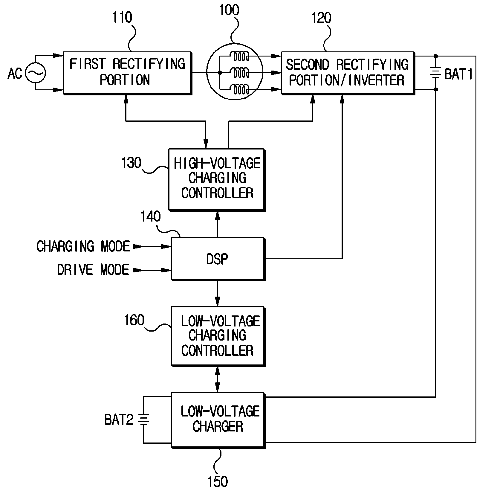
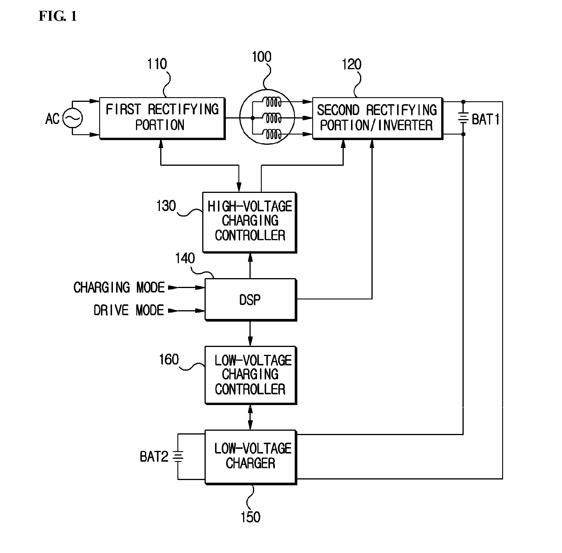
[0046]FIG.1 is a schematic block diagram showing an entire construction of the present disclosure. Here, a numeral reference 100 denotes a 3-phase motor. The 3-phase motor 100 has a Y-connected coil.

[0047]Numeral reference 110 denotes a first rectifying portion. For example, the first rectifying portion 110 is a buck-type single-phase rectifier that is coupled with the 3-phase motor 100 and rectifies a single-phase alternating power AC in a buck-typ...


PUM


Abstract

Disclosed is a charger including a first rectifying portion that rectifies an alternating power and outputs the rectified power to a neutral point of a 3-phase motor; a second rectifying portion / inverter that charges output power of the first rectifying portion in a high-voltage battery in a charging mode and drives the 3-phase motor by switching the charged power of the high-voltage battery in a drive mode; a high-voltage charging controller that controls the first rectifying portion and second rectifying portion / inverter so as to charge the high-voltage battery in the charging mode; and a DSP (Digital Signal Processor) that controls the second rectifying portion / inverter so as to drive the 3-phase motor in the drive mode, and controls the high-voltage charging controller so as to charge the high-voltage battery in the charging mode.

Description

[0001]Pursuant to 35 U.S.C.§119 (a), this application claims the benefit of earlier filing date and right of priority to Korean Patent Application No. 10-2010-0006702, filed on Jan. 25, 2010, the contents of which are hereby incorporated by reference in their entirety.BACKGROUND OF THE DISCLOSURE[0002]1. Field of the Invention[0003]The present disclosure relates to a charger that charges a high-voltage battery and a low-voltage battery, the high-voltage battery providing a 3-phase motor equipped in an electric vehicle with a driving power, the low-voltage battery providing electronic elements and a lamp device equipped in the electric vehicle with an operating power. More particularly, the present disclosure relates to a charger that charges the high-voltage battery, charges the low-voltage battery using the power charged in the high-voltage battery while controlling a power factor of an input commercial AC (alternating Current) power at about 1 by operating a buck-type single-phase...

Claims


Application Information

Patent Timeline
Patent Type & Authority Applications(United States)
IPC IPC(8): H02J7/00
CPCB60L11/1868Y02T10/7066Y02T10/7005H02J7/022B60L58/20H02J7/02H02J2207/20Y02T10/70
Inventor YANG, CHUN SUKLEE, JAE HO
Owner LS IND SYETEMS CO LTD
Why Eureka
Try Eureka