Magnetic recording/reproduction head
a head and magnetic technology, applied in the field of magnetic head, can solve problems such as base line shift in waveforms, and achieve the effect of high linear density and good bit error ra
- Summary
- Abstract
- Description
- Claims
- Application Information
AI Technical Summary
Benefits of technology
Problems solved by technology
Method used
Image
Examples
first embodiment
[0073]FIG. 38 illustrates a magnetic head including a read head and a perpendicular recording head. On a base 50 serving also as a slider are a lower magnetic shield 41, a magneto-resistive effect laminated film 30, an upper magnetic shield 42, a return pole 64, a coil 63, a main pole 61, and a wraparound shield 62 which is a magnetic shield enclosing the main pole, all of which form an ABS (Air bearing surface) surface 81. The figure illustrates a structure in which the upper magnetic shield and the return pole are provided separately, but a structure in which both the upper magnetic shield and the return pole are integrated is not regarded as a departure from the spirit and scope of the present invention. Further, a structure without the wraparound shield 62 is not regarded as a departure from the spirit and scope of the present invention.
[0074]FIG. 39 illustrates a configuration example of a magnetic recording / reproducing apparatus. A disk 91 which holds a recording medium 95 whi...
second embodiment
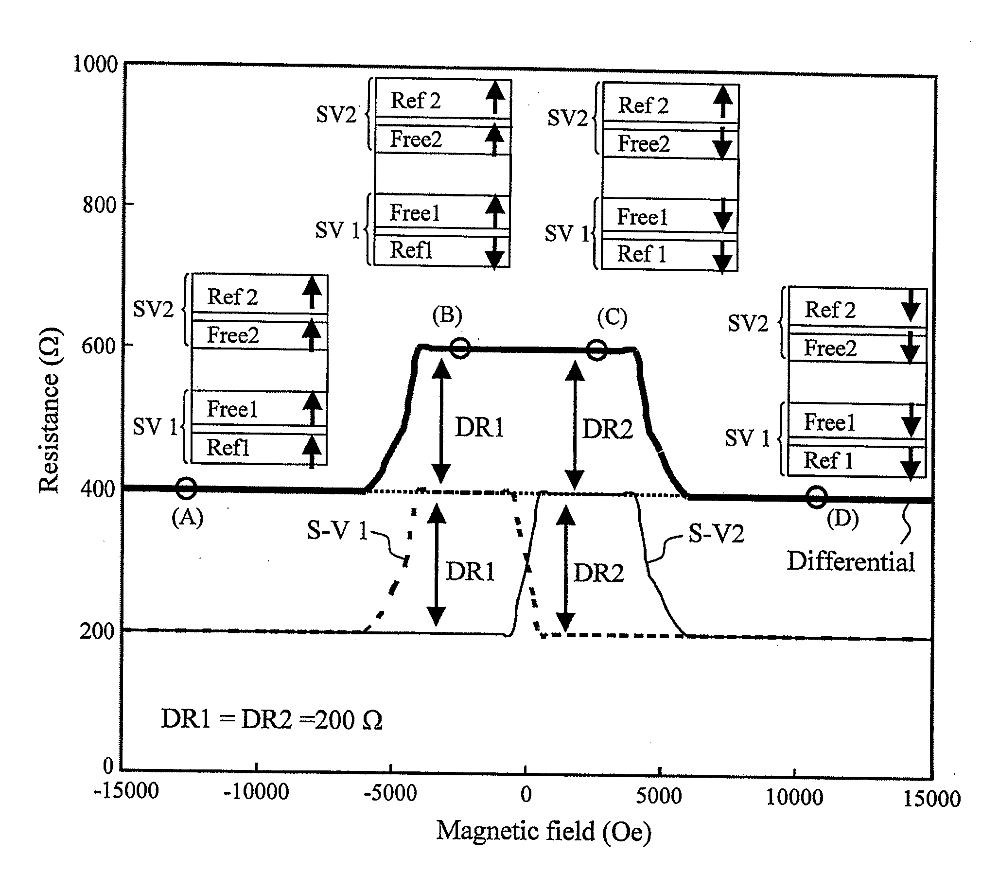
[0104]Another configuration example of the present invention will be described. Unlike the first embodiment, the present configuration example is configured such that DR1 is smaller than DR2. One of the reasons that the maximum resistance change of the second magneto-resistive sensor is larger is that the second magneto-resistive film has a good underlying orientation. This is because the underlying film of the second magneto-resistive film corresponds to the intermediate layer between the first magneto-resistive film and the second magneto-resistive film and has a relatively thick film thickness of several 10 nm which tends to have a good orientation.
[0105]Like the configuration of the first embodiment, the present configuration example can reduce the base line shift caused by the difference between DR1 and DR2 by controlling HB1 and HB2. FIG. 14 illustrates the base line shift distributions of a plurality of heads to which the present invention is not applied (experiment 2) and a ...
third embodiment
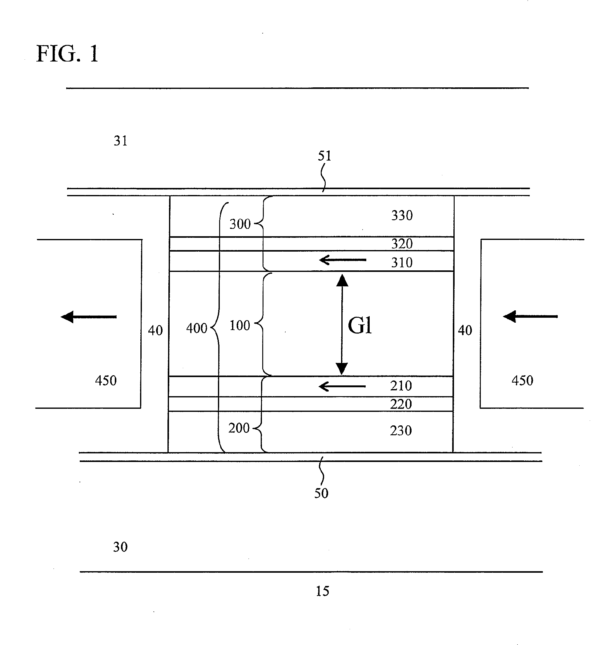
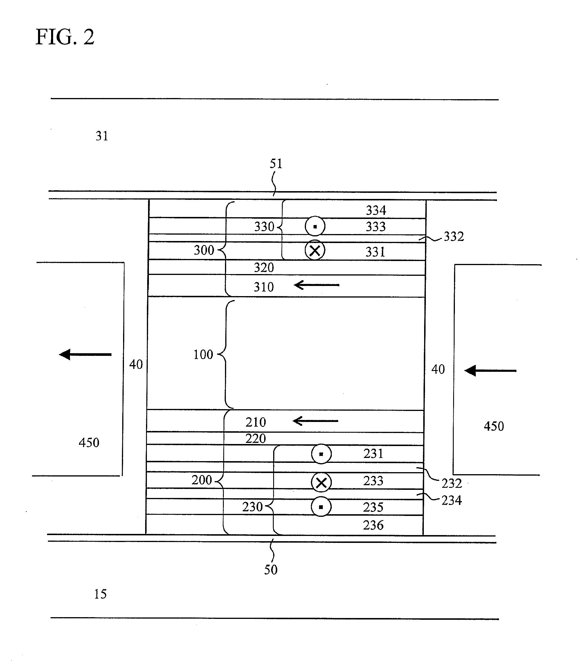
[0108]Another configuration example of the present invention will be described. Like the first embodiment, the present configuration example can reduce the base line shift in the differential read head in which DR1 is larger than DR2. In the third embodiment, a particularly detailed description will be given of the method of controlling the magnetic domain control field of the two magneto-resistive sensors not described in the first embodiment. Regarding the method of controlling the magnetic domain control field, the relative positional relation and the geometric shape of the magnetic domain control layer 450 and the first and second free layers of the differential read head are set. The configuration of the two magneto-resistive sensors and the differential gap layer in the present configuration example is the same as that of the first embodiment, and thus the description duplicating the first embodiment will be omitted. In the present configuration example, in order to control th...
PUM
 Abstract
Description
Claims
Application Information
 - R&D
- Intellectual Property
- Life Sciences
- Materials
- Tech Scout
- Unparalleled Data Quality
- Higher Quality Content
- 60% Fewer Hallucinations
Browse by: Latest US Patents, China's latest patents, Technical Efficacy Thesaurus, Application Domain, Technology Topic, Popular Technical Reports.
© 2025 PatSnap. All rights reserved.Legal|Privacy policy|Modern Slavery Act Transparency Statement|Sitemap|About US| Contact US: help@patsnap.com


