System and method to manage power usage

Inactive Publication Date: 2011-07-28
THE POWERWISE GRP
View PDF103 Cites 34 Cited by
  • Summary
  • Abstract
  • Description
  • Claims
  • Application Information

AI Technical Summary

Benefits of technology

[0021]During a first predetermined time period, such as when blackouts are not anticipated, a digital signal processor (DSP) controls an IGBT/FET-based device to supply a predetermined voltage that is less than the AC incoming line voltage or mains input voltage. Phase input connections are provided for inputting analog signals into the device and system. A magnetic flux concentrator or a current transformer sense

Problems solved by technology

If the load has not been adequately reduced after a predetermined amount of time the DSP may shut off power.
If the lo

Method used


Image

  • System and method to manage power usage
  • System and method to manage power usage
  • System and method to manage power usage

Examples


first embodiment

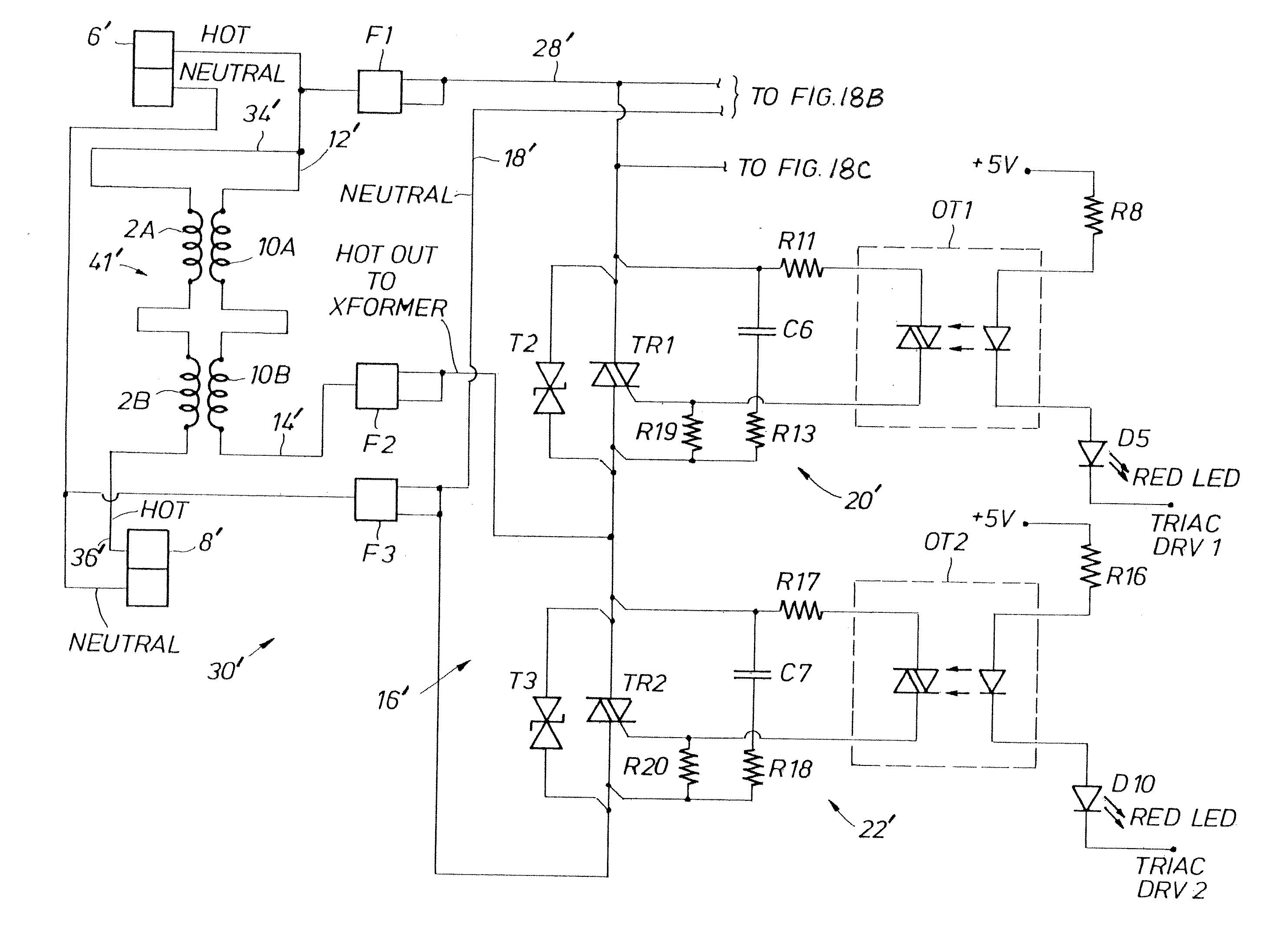
[0217]FIGS. 18A-18C taken together show a voltage booster apparatus 30′ configured for 220 / 230 Voltage root mean square (Vrms). The voltage booster apparatus 30′ may also be configured for 120 / 127 Vrms. FIG. 18A shows transformer 41′ and switch 16′. Switch 16′ comprises first relay 20′ and second relay 22′. FIG. 18B shows power supply 24′. FIG. 18C shows microprocessor 26′. Turning to FIG. 18A, secondary windings 2A and 2B of transformer 41′ are in series between the input line hot terminal 6′ and the output line hot terminal 8′. Hot input line 34′ to hot output line 36′ passes through the transformer secondary windings 2A and 2B at all times, and is not switched. To configure for 120 / 127 Vrms, then the secondary windings 2A and 2B would be in parallel. Alternatively, the transformer may be a single voltage type specifically for 230 V, 120 V, or any other voltage range.

[0218]The transformer primary windings 10A and 10B have first end or first line 12′ connected to hot input terminal...

second embodiment

[0226]FIGS. 19-19C taken together show a voltage booster apparatus 54′. FIG. 19 shows exemplary 120 Volt transformer 66′. FIG. 2A shows exemplary 230 Volt transformer 68′. The wiring arrangements are different in FIGS. 19 and 19A. The windings for the 120 Volt transformer 66′ (FIG. 19) are in parallel, and the windings for the 230 Volt transformer 68′ (FIG. 19A) are in series. The same transformer 66′, 68′ may be used for 120 Volt and for 230 Volt by configuring the wiring arrangements as shown: parallel for 120 Volts and series for 230 Volts. However, different 66′, 68′ transformers may be used as well. The transformer may be a single voltage type specifically for 230 V, 120 V, or any other voltage range. Other transformers with different current ratings are also contemplated. Only one such transformer 66′, 68′ would be connected with the system at a time. FIG. 19B shows two isolated DC power supplies (50′, 52′), power supply 63′, and power supply regulation circuitry 64′. FIG. 19C...


PUM


Abstract

A system and method are provided for managing electrical power usage. During a predetermined time period, such as during blackout conditions, a digital signal processor (DSP) controls an IGBT/FET-based device to supply an allocated amount of power. When the consumed amount of power exceeds the allocated amount, the DSP shuts off the power. Alternatively, the system provides a signal to reduce the consumed power. If sufficient load has not been reduced after a predetermined amount of time, the power is shut off. Further alternatively or in addition, the DSP may shut off power to predetermined electrical outlets, while providing power to other electrical outlets, to reduce the power usage to the predetermined amount. During other time periods, the DSP controls the IGBT/FET device to provide a predetermined voltage that is less than the AC incoming line voltage. When the voltage drops below the predetermined voltage, such as during brownout conditions, a microprocessor controls an electronic switch on the primary windings side of a transformer system to provide a boosted output voltage.

Description

CROSS-REFERENCE TO RELATED APPLICATIONS[0001]This application claims the benefit of U.S. Provisional Application No. 61 / 432,399 filed Jan. 13, 2011, which application is hereby incorporated by reference for all purposes in its entirety. This application is a continuation-in-part of (1) co-pending U.S. application Ser. No. 12 / 185,442 filed Aug. 4, 2008, which claims the benefit of U.S. Provisional Application No. 60 / 964,587 filed Aug. 13, 2007, U.S. Provisional Application No. 60 / 966,124 filed Aug. 24, 2007, U.S. Provisional Application No. 61 / 009,844 filed Jan. 3, 2008, U.S. Provisional Application No. 61 / 009,846 filed Jan. 3, 2008, U.S. Provisional Application No. 61 / 009,845 filed Jan. 3, 2008, and U.S. Provisional Application No. 61 / 009,806 filed Jan. 3, 2008; (2) co-pending U.S. application Ser. No. 12 / 893,539 filed Sep. 29, 2010; and (3) co-pending International Application No. PCT / US10 / 50714 filed Sep. 29, 2010, all of which applications are hereby incorporated by reference for...

Claims


Application Information

Patent Timeline
IPC IPC(8): H02M7/06
CPCH02J1/14G05B15/02G01R21/00G05F1/40H02J3/00H02J13/00
Inventor LUMSDEN, JOHN L.ZAGA, RAFAEL E.
Owner THE POWERWISE GRP
Why Eureka
Try Eureka