Motor Shaft Vibration Isolator for Electric Submersible Pumps

a technology of motor shaft and isolator, which is applied in the direction of elastic bearings, mechanical equipment, rigid support of bearing units, etc., can solve the problems of increasing well depth or discharge pressure, reducing capacity, and oil production will continue to fall, so as to improve bearing life, improve heat dissipation in oil, and reduce bearing costs

Inactive Publication Date: 2011-07-28
BAKER HUGHES INC
View PDF11 Cites 19 Cited by
  • Summary
  • Abstract
  • Description
  • Claims
  • Application Information

AI Technical Summary

Benefits of technology

[0017]A vibration dampening system for a motor shaft in an ESP uses axially extending arms in one or opposed directions from a fixed portion of a motor shaft bearing. The weights can have their location adjusted to tune the device to the natural frequencies of the rotating shaft and to add an ability to address vibration in more than one plane. Openings are provided in the support for the arms that hold the weight so that arm vibration can create turbulence and improve heat dissipation in the oil for improved bearing life. Bearing cost can be reduced using more economical materials without sacrificing bearing life.

Problems solved by technology

Like all other centrifugal pumps, an increase in well depth or discharge pressure will reduce the capacity.
However, they also present problems that must be solved, such as gas interference and sand production.
Given time, however, oil production will continue to fall and water production will increase.
These pumps were traditionally installed in high-volume artificial-lift applications that are seldom appropriate for deliquifying gas wells.
ESPs offer the highest yield of most deep-well artificial lift systems, but suffer the highest frequency of expense and repair.
High percentages can cause gas locking in the pump mechanism, resulting in a serious decrease in flow delivery—requiring the entire production string to be pulled from the well and re-primed.
One issue with these motors is bearing life, which is affected by vibration.
Another issue is the limited space around the motor shaft in the motor housing in which any device that dampens such vibration can be disposed.
These weights were all interdependent because they were fixated to the sleeve and their positions with respect to the sleeve could not be simply adjusted for tuning purposes.

Method used


Image

  • Motor Shaft Vibration Isolator for Electric Submersible Pumps
  • Motor Shaft Vibration Isolator for Electric Submersible Pumps
  • Motor Shaft Vibration Isolator for Electric Submersible Pumps

Examples


Embodiment Construction

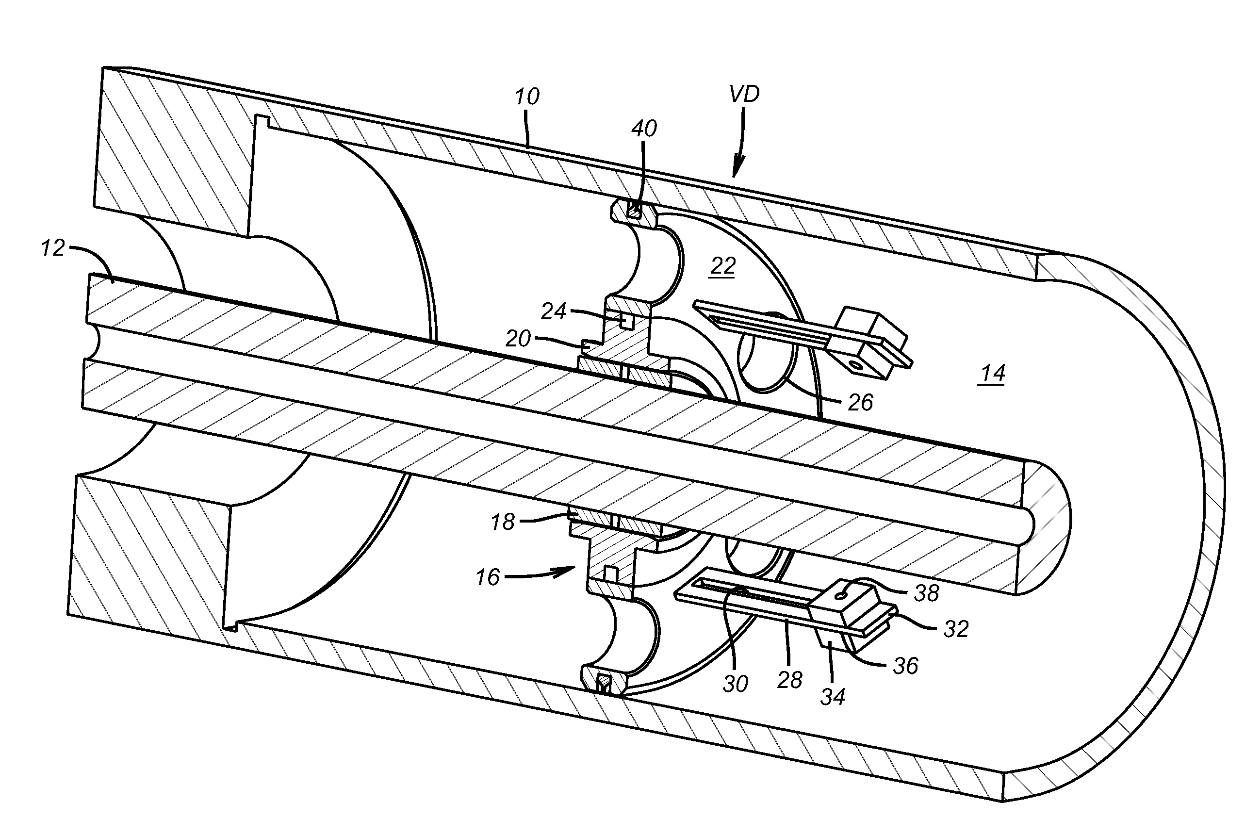
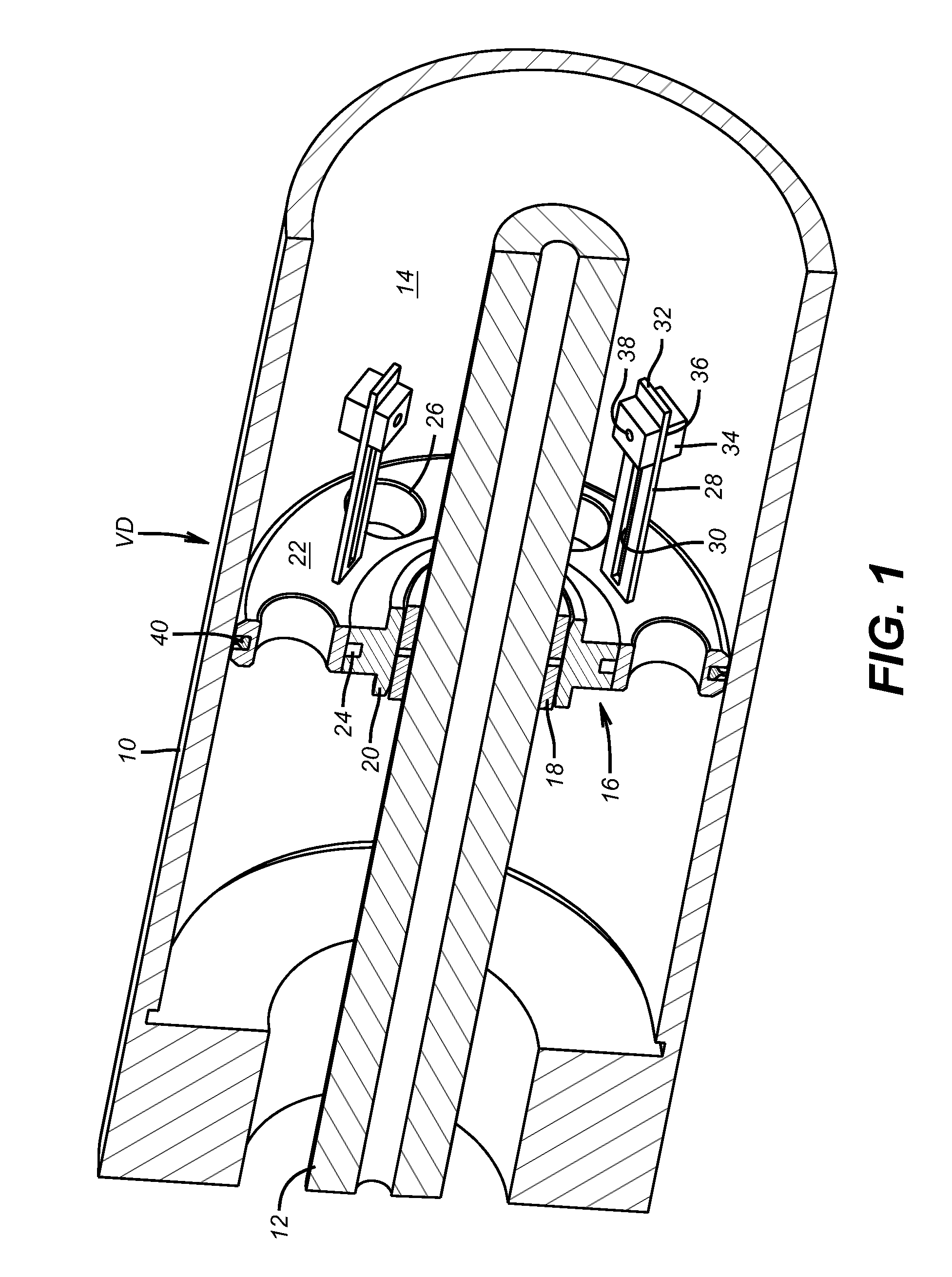
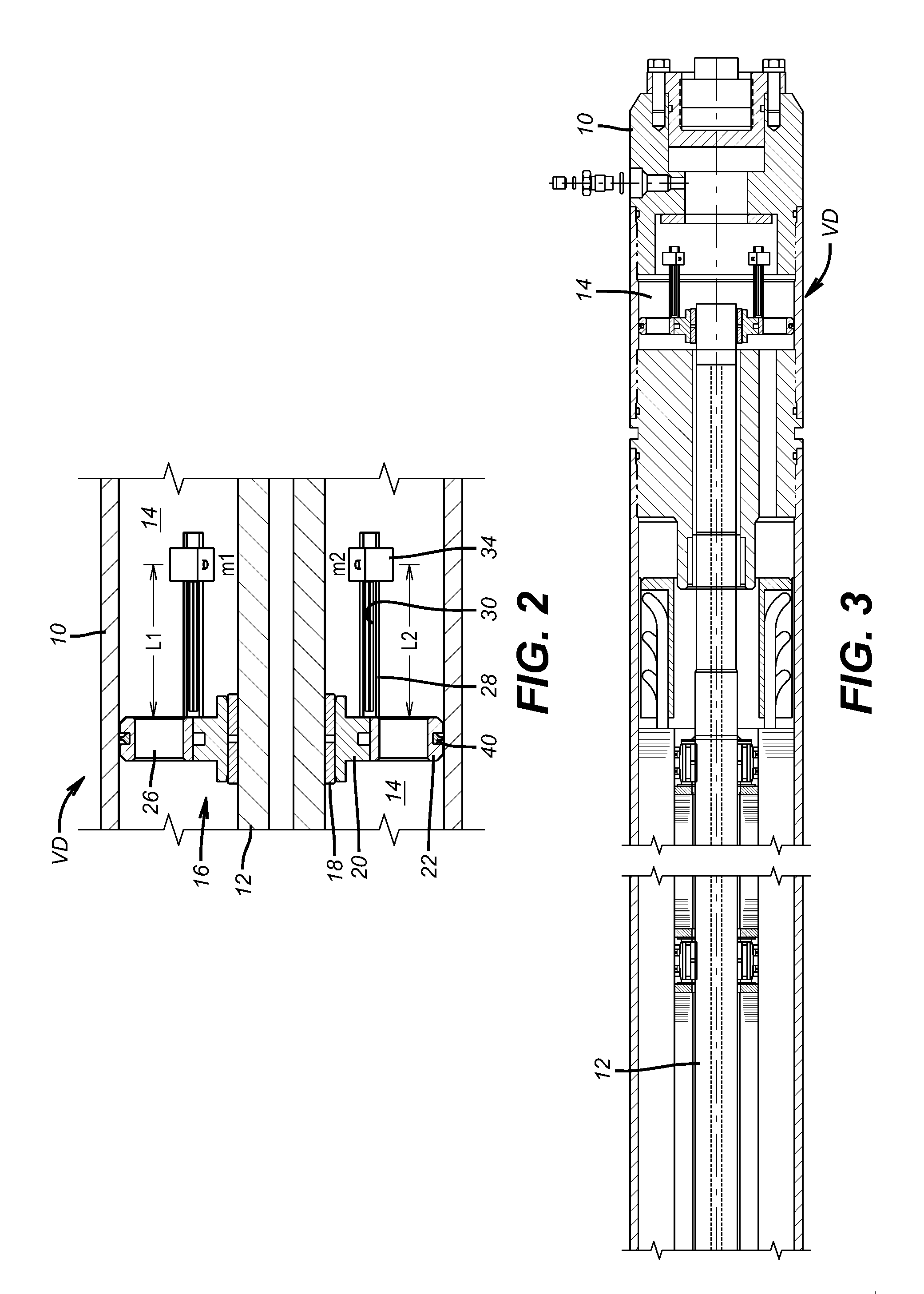
[0021]FIG. 1 illustrates a motor shaft 12 in an elongated motor housing 10 for an ESP. That same housing 10 is also shown, in part, in FIG. 3 to locate the vibration dampener VD. The annular space 14 around the shaft 12 contains a lubricant for the bearing 16. The bearing 16 has an inner sleeve 18 supported by inner ring 20 that rotate with the shaft 12. The outer member 22 is secured in the housing 10 and supports the vibration dampener VD. A series of rollers are at the interface of the inner ring 20 and the outer member 22. A series of openings 26 are disposed in the outer member 22 to allow lubricating oil (not shown) that is in annular space 14 to move axially in opposed directions within the housing 10. Outer member 22 has a series of axially extending arms 28 that preferably extend at 90 degrees to the outer member or parallel to shaft 12. An elongated slot 30 runs the substantial length of the arm 28 and can optionally run to its end 32. A weight 34 has a slot 36 to allow th...


PUM


Abstract

A vibration dampening system for a motor shaft in an ESP uses axially extending arms in one or opposed directions from a fixed portion of a motor shaft bearing. The weights can have their location adjusted to tune the device to the natural frequencies of the rotating shaft and to add an ability to address vibration in more than one plane. Openings are provided in the support for the arms that hold the weight so that arm vibration can create turbulence and improve heat dissipation in the oil for improved bearing life. Bearing cost can be reduced using more economical materials without sacrificing bearing life.

Description

FIELD OF THE INVENTION[0001]The field of this invention is devices that reduce shaft vibration by absorbing the vibration and using weights supported at a distance from the shaft that respond to the frequency of excitation coming from the shaft to take up the vibration and more particularly application of this principle in highly confined spaces such as a motor for an electric submersible pump or ESP.BACKGROUND OF THE INVENTION[0002]Most producing oil fields utilize an electrically driven downhole pumping system to bring oil to the surface. The pump typically comprises several staged centrifugal pump sections that can be specifically configured to suit the production and wellbore characteristics of a given application. ESP systems are a common artificial-lift method, providing flexibility over a range of sizes and output flow capacities. ESPs are typically used in older reservoirs on wells with high water cuts (percentage of water to oil).[0003]ESPs provide cost effective production...

Claims


Application Information

Patent Timeline
Patent Type & Authority Applications(United States)
IPC IPC(8): F16F15/02F16C3/00
CPCY10T464/50F16F15/322F16F15/10
Inventor PRIETO, CARLOS A.
Owner BAKER HUGHES INC
Why Eureka
Try Eureka