

Hollow poppet valve and method of manufacturing the same
a hollow and poppet technology, applied in the direction of manufacturing tools, machines/engines, welding apparatus, etc., can solve the problems of increasing the manufacturing cost of the poppet, reducing the hardness of the surface of the seat-abutment portion, and forming on the fillet portion, etc., to achieve easy manufacturing, improve strength-weight characteristics, and cost-effective
Active Publication Date: 2011-08-04
NITTAN VALVE CO LTD
View PDF5 Cites 12 Cited by
- Summary
- Abstract
- Description
- Claims
- Application Information
AI Technical Summary
Benefits of technology
[0004]However, since the poppet valve of Re-published patent WO 00 / 47876 (shown in FIGS. 2 and 13) has such a thick open edge of the fillet portion as mentioned above, it has less weight alleviation effect. Moreover, the structure shown in FIG. 2 of Re-published patent WO 00 / 47876 requires a process of fabricating a stepped or depressed portion for receiving the cap in the open periphery of the fillet portion, which adds a further manufacturing cost to the poppet.
[0041]It is noted that in the invention the cap member can be smoothly placed in position and mated to the seat-abutment portion so that the cap member can be accurately and quickly welded to a predetermined position of the fillet portion.
Problems solved by technology
H6-299816 suffers a problem that the hardness of the surface of the seat-abutment portion, formed on the fillet portion, is decreased by welding heat due to the fact that the seat-abutment portion is formed closely to the open end thereof welded to the cap member.
H6-299816 suffer another problem that the caps are thick and therefore heavy, which is an obstacle to reduce the weight of the poppet valve.
Moreover, the structure shown in FIG. 2 of Re-published patent WO 00 / 47876 requires a process of fabricating a stepped or depressed portion for receiving the cap in the open periphery of the fillet portion, which adds a further manufacturing cost to the poppet.
Method used
View moreImage
Smart ImageViewing Examples

Examples
second embodiment
[0045]FIG. 4 shows a vertical cross section of a hollow poppet valve in accordance with the invention.
third embodiment
[0046]FIG. 5 shows a vertical cross section of a hollow poppet valve in accordance with the invention.
fourth embodiment
[0047]FIG. 6 shows a vertical cross section of a hollow poppet valve in accordance with the invention.
Login to View More PUM
| Property | Measurement | Unit |
|---|---|---|
| thickness | aaaaa | aaaaa |
| thickness | aaaaa | aaaaa |
| thickness t2 | aaaaa | aaaaa |
Abstract
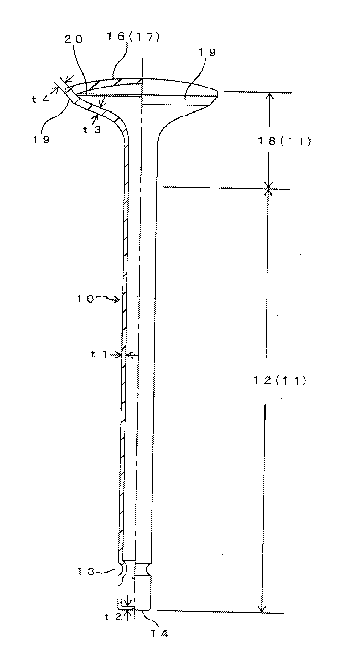
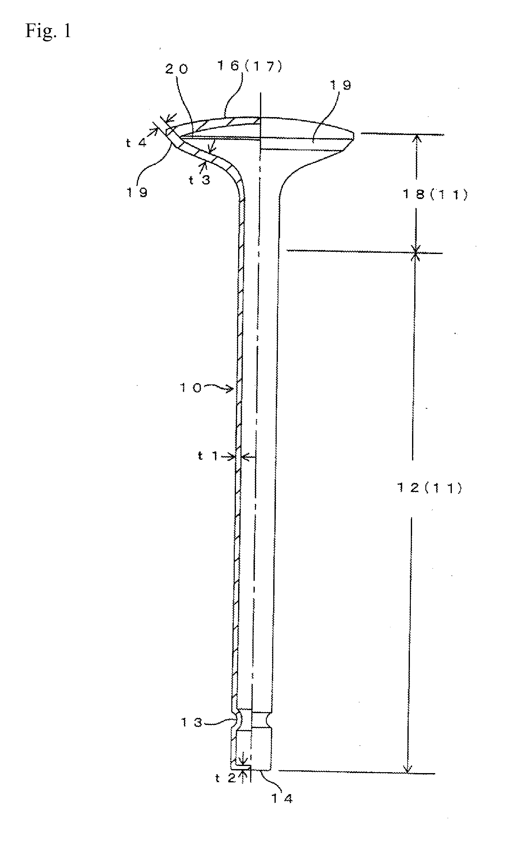
A hollow poppet valve has a stem portion provided at one end thereof with a tip portion; a cap portion; and a flared fillet portion formed between the stem portion and the cap portion, wherein at least a part of the stem portion that connects to the fillet portion is a thin hollow cylindrical member, and the cap member is welded to the fillet portion. The cap member is thin and has an arcuate axial cross section. It is laser-beam welded to the seat-abutment portion formed at the open end of the fillet portion such that a weld bead is formed along the inner periphery of the interface of the mated ends of the members. The weld bead adds an extra weld depth to the weld, which increases the modulus of section of the welded regions of the cap member and the fillet portion and enhances their welding strength.
Description
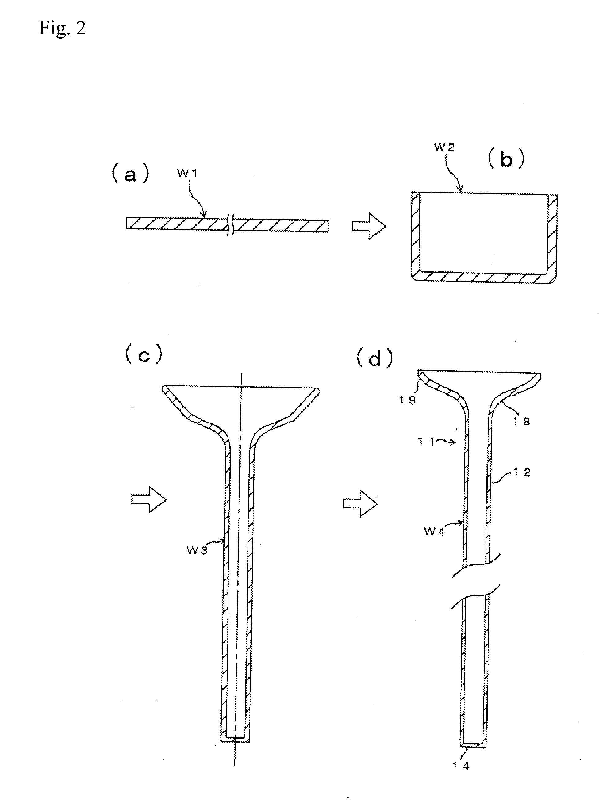
TECHNICAL FIELD[0001]This invention relates to a light-weight hollow poppet valve for use with an internal combustion engine, the valve having: a stem portion provided at one end thereof with a tip portion; a cap portion for receiving combustion pressure; and a transitional flared fillet portion provided between the stem portion and the cap portion, and, more particularly, to a thin hollow cylindrical poppet valve having a thin hollow cylindrical member comprising of a fillet portion and a stem portion integral with the fillet portion, with a cap member, serving as the cap portion, welded to the fillet portion. The invention also relates to a method of manufacturing such poppet valve.BACKGROUND OF THE INVENTION[0002]JPA Laid Open No. H6-299816 (FIGS. 2, 7, 8, 10-12) and Re-published patent WO 00 / 47876 (FIGS. 2, 13) cited below disclose hollow poppet valves and methods of manufacturing the same, in which a metal plate is drawn to form an integral thin hollow cylindrical stem portion ...
Claims
Login to View More Application Information
Patent Timeline
 Patent Type & AuthorityApplications(United States)
IPC IPC(8): F01L3/00B21D51/16F16K1/36
CPCB21K1/22B23P15/002F01L3/14Y10T29/49307F01L2103/00Y10T29/49405F01L3/20F01L2820/01F01L2303/00B23K15/00B23K26/21F01L3/02
InventorENDO, HIROMITSU
OwnerNITTAN VALVE CO LTD