Gas fuel injection control device of engine for vehicle

a technology of control device and fuel injection, which is applied in the direction of electric control, machines/engines, liquid fuel feeders, etc., can solve the problems of affecting the operation of the engine, excess or deficiency of fuel injection quantity, and failure to appropriately calculate the pressure correction coefficient, etc., to achieve the effect of improving the accuracy of gas fuel injection control

Inactive Publication Date: 2011-08-04
SUZUKI MOTOR CORP
View PDF13 Cites 24 Cited by
  • Summary
  • Abstract
  • Description
  • Claims
  • Application Information

AI Technical Summary

Benefits of technology

[0012]An object of the invention is to improve the accuracy of gas fuel injection control by accurately correcting an intake pipe internal pressure which greatly affects the correction of the injection quantity of gas fuel injected from a fuel injection valve.

Problems solved by technology

Incidentally, the gas fuel injection control device of an engine for vehicle in the related art performs the same filtering in the processing of the intake pipe internal pressure value irrespective of the engine in the constant-speed operation state or in the transition operation state, and therefore has following problems.
One of the problems is that, in the constant-speed operation, there is not a large difference between the differential pressure detected by the gas fuel injection control device between the intake pipe internal pressure and the gas pressure upstream of the fuel injection valve and the differential pressure in the regulator, whereas at the abrupt acceleration operation or the abrupt deceleration operation, a difference occurs between the differential pressure detected by the gas fuel injection control device and the differential pressure in the regulator because of a response delay of the regulator, resulting in failure to appropriately calculate the pressure correction coefficient.
Performing the filtering of the intake pipe internal pressure in consideration of the response delay of the regulator at the transition operation as measures causes another problem of failing to detect the pulsation of the intake pipe internal pressure and the gas pressure at the constant-speed operation, resulting in failure to appropriately calculate the pressure correction coefficient.
Another problem is that because the same filtering is performed at the constant-speed operation and the transition operation, it is impossible to appropriately correct either the pressure correction at the constant-speed operation or the pressure correction at the transition operation, causing excess or deficiency of the fuel injection quantity and affecting the operation of the engine.

Method used


Image

  • Gas fuel injection control device of engine for vehicle
  • Gas fuel injection control device of engine for vehicle
  • Gas fuel injection control device of engine for vehicle

Examples


embodiment

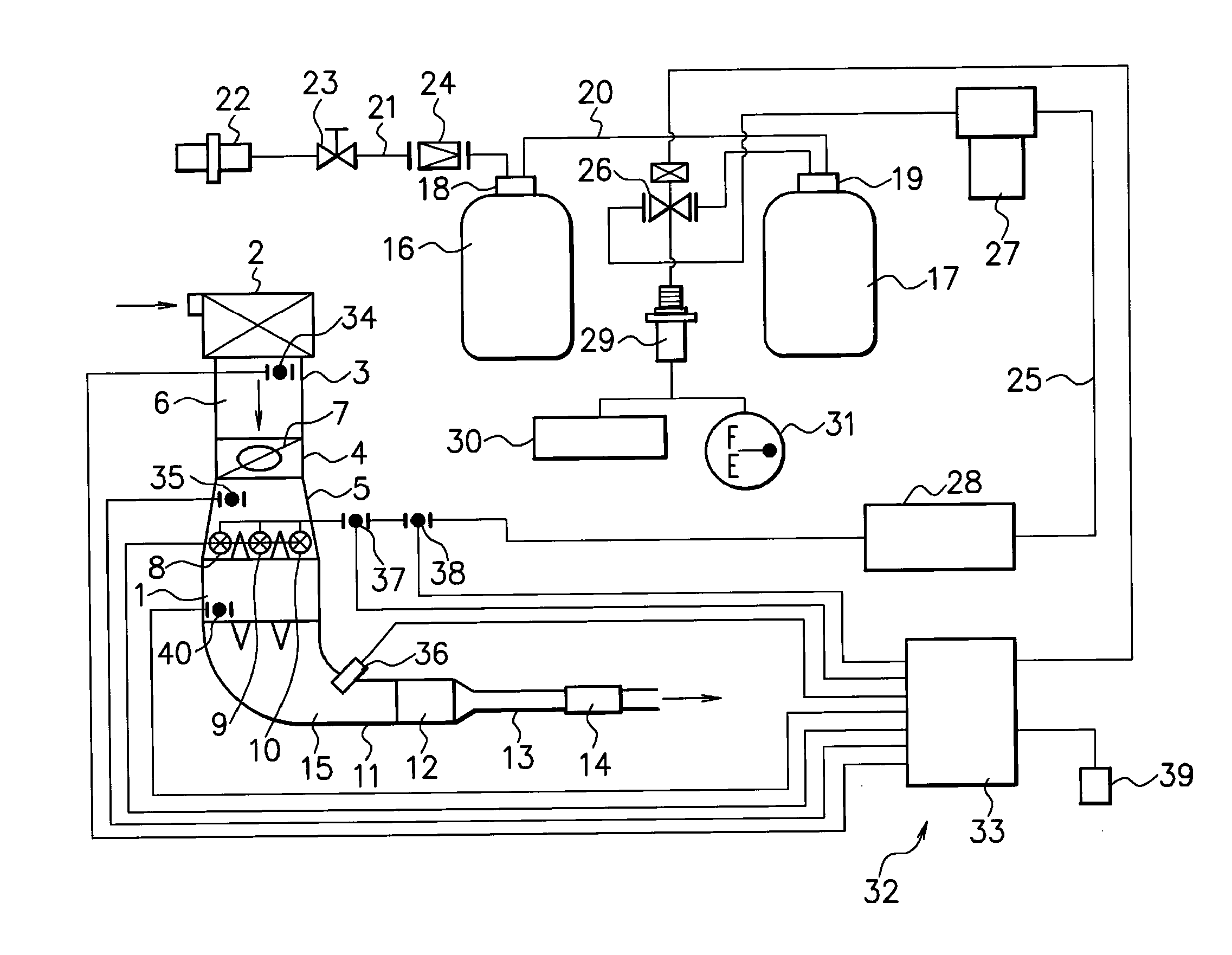
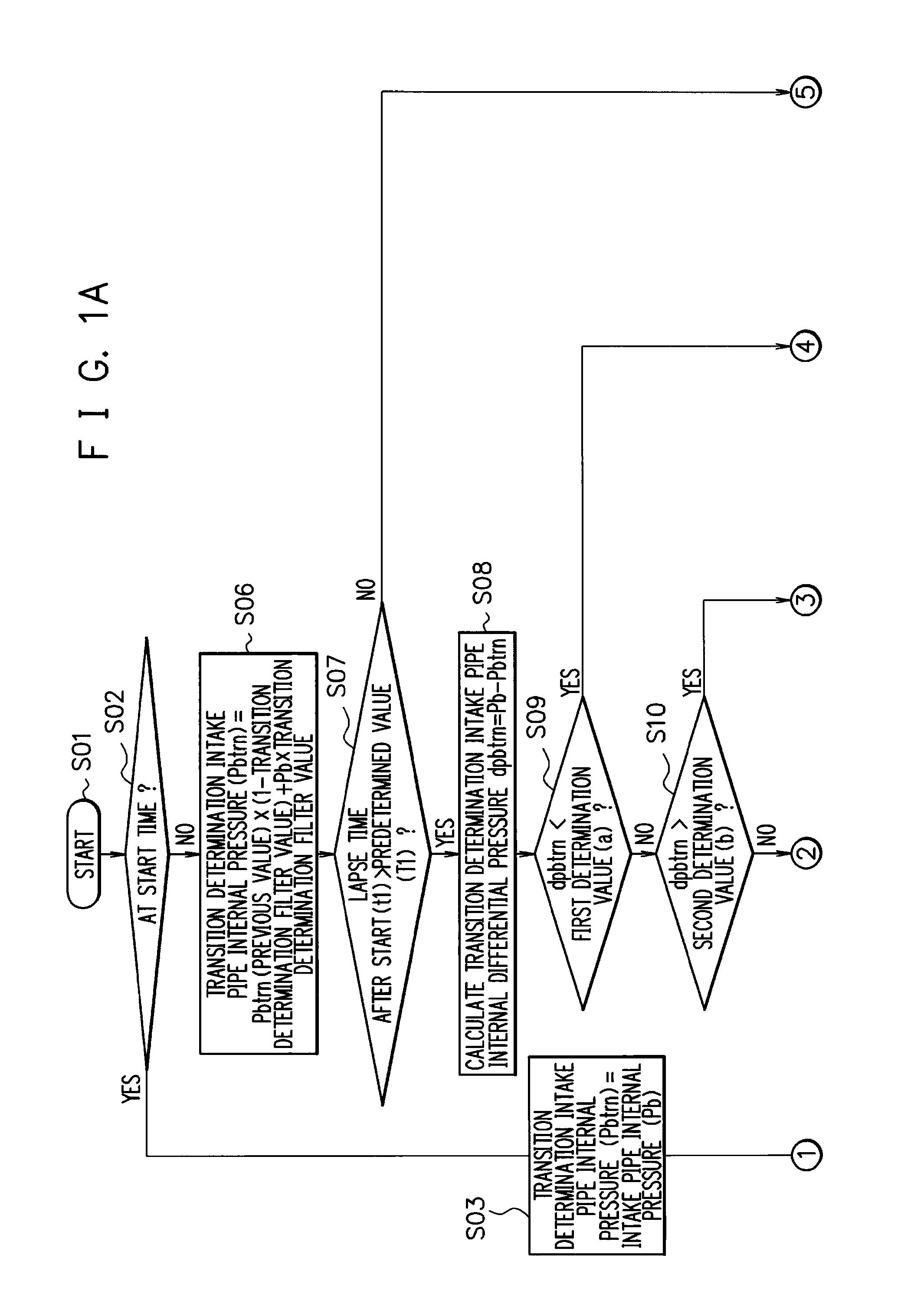
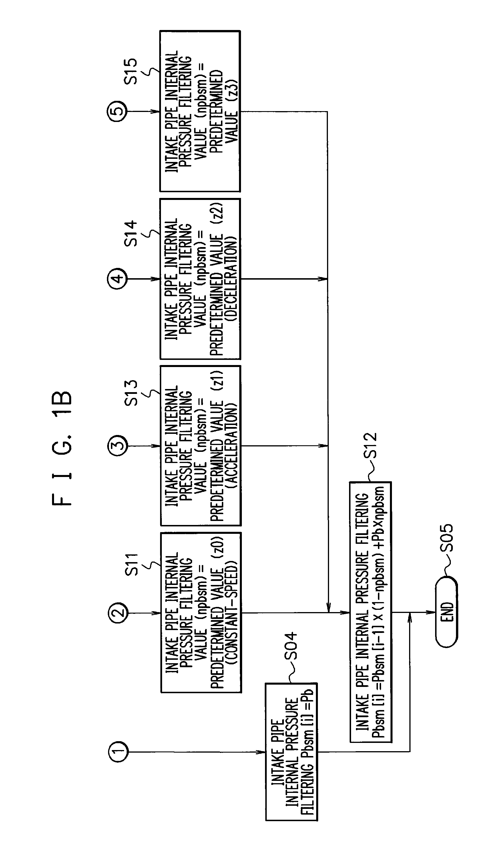
[0019]FIG. 1A to FIG. 3 illustrate the embodiment of the invention. In FIG. 3, numeral 1 denotes an engine for vehicle (hereinafter, described as an “engine”). The engine 1 has, for example, three cylinders and includes, as an intake system, an air cleaner 2, an intake pipe 3, a throttle body 4, and an intake manifold 5 and thereby communicates an intake passage 6 with the cylinders. In the intake passage 6 of the throttle body 4, a throttle valve 7 is provided. A first fuel injection valve 8 to a third fuel injection valve 10 corresponding to the respective cylinders are attached to the intake manifold 5. Further, the engine 1 includes, as an exhaust system, an exhaust manifold 11, a three-way catalyst 12, an exhaust pipe 13, and a muffler 14 and thereby communicates an exhaust passage 15 with the cylinders.

[0020]The engine 1 is supplied with a gas fuel stored in two fuel containers such as a first fuel container 16 and a second fuel container 17. The first and second fuel containe...


PUM


Abstract

A control unit performs control to previously set a transition determination filter value for determining a transition operation state of an engine, and calculate a transition determination intake pipe internal pressure from the transition determination filter value, an intake pipe internal pressure that was detected last time, and an intake pipe internal pressure that has been detected this time, and when a lapse time after start of the engine exceeds a predetermined value, calculate a transition determination intake pipe internal differential pressure from the intake pipe internal pressure that has been detected this time and the transition determination intake pipe internal pressure, set an intake pipe internal pressure filtering value based on the transition determination intake pipe internal differential pressure, and calculate an intake pipe internal pressure that is used for gas fuel injection control this time from the intake pipe internal pressure filtering value, the intake pipe internal pressure that has been detected this time, and an intake pipe internal pressure that was used for gas fuel injection control last time.

Description

CROSS-REFERENCE TO RELATED APPLICATIONS[0001]This application is based upon and claims the benefit of priority of the prior Japanese Patent Application No. 2010-023273, filed on Feb. 4, 2010, the entire contents of which are incorporated herein by reference.BACKGROUND OF THE INVENTION[0002]1. Field of the Invention[0003]The present invention relates to a gas fuel injection control device of an internal combustion engine for vehicle, and more specifically to a gas fuel injection control device of an engine for vehicle in which the accuracy of a calculating method of an intake pipe internal pressure for use in an injection quantity control of a gas fuel in a constant-speed operation and transition operation states such as acceleration and deceleration operation states of the engine.[0004]2. Description of the Related Art[0005]A gas fuel injection control device of an engine for vehicle that is supplied with a gas fuel such as CNG (compressed natural gas) reduces the pressure of the ga...

Claims


Application Information

Patent Timeline
Patent Type & Authority Applications(United States)
IPC IPC(8): F02M69/04
CPCF02D41/0025F02D41/061F02D41/107F02D2200/0602F02D2200/0406F02D2200/0408F02D2041/1432
Inventor SASAKI, TAKAMITSU
Owner SUZUKI MOTOR CORP
Why Eureka
Try Eureka