Optical receiving apparatus and optical transmission system

a technology of optical receiving apparatus and optical transmission system, which is applied in the direction of transmission, electromagnetic transmission, transmission monitoring, etc., can solve the problems of long time, inability to quickly stabilize the control amount of the delayed interferometer and the variable dispersion compensator, and the search takes a relatively long time. , to achieve the effect of reducing the effect of polarization mode dispersion and short tim

Inactive Publication Date: 2011-08-04
FUJITSU LTD
View PDF3 Cites 2 Cited by
  • Summary
  • Abstract
  • Description
  • Claims
  • Application Information

AI Technical Summary

Benefits of technology

[0022]The present invention has been made in view of the foregoing circumstances, and a purpose thereof is to provide an optical receiving apparatus and an optical transmission

Problems solved by technology

And the problem is that the search takes a relatively long time and therefore the control amounts for the delayed interferometer and the variable dispersion compensator cannot be stabilized quickly.
However, since it takes a long time to measure an error rate so low as 1×10⁻¹² (e.g., 25 seconds to measure the error rate of 1×10⁻¹² for received signals of 40 Gb/s), at least several minutes are required to find the optimal point P within the range of control amount where the error rate is 1×10⁻¹² or below.
If the control amount is set at point P′ away from the real op

Method used


Image

  • Optical receiving apparatus and optical transmission system
  • Optical receiving apparatus and optical transmission system
  • Optical receiving apparatus and optical transmission system

Examples


Embodiment Construction

[0045]The invention will now be described by reference to the preferred embodiments. This does not intend to limit the scope of the present invention, but to exemplify the invention.

[0046]The invention will now be described based on preferred embodiments with reference to the accompanying drawings. Note that like numbers refer to like elements throughout.

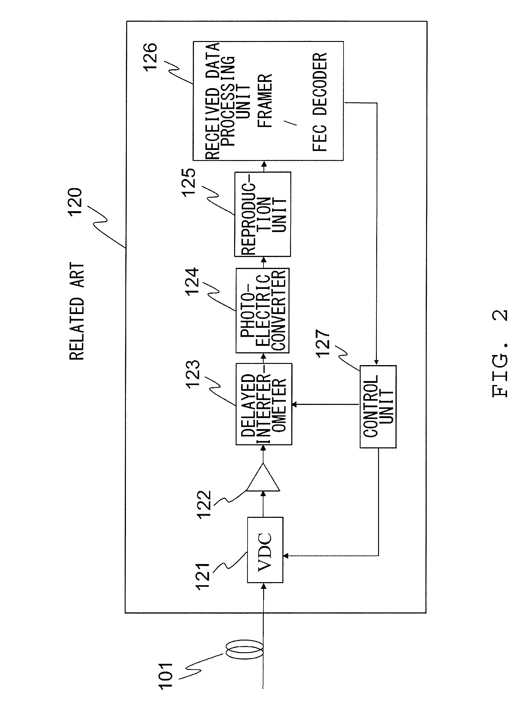
[0047]FIG. 8 is a block diagram showing a structure of an optical receiving apparatus 10 according to a first embodiment of the present invention.

[0048]As shown in FIG. 8, the optical receiving apparatus 10 according to the first embodiment includes a polarization control unit 20, a variable dispersion compensator (VDC) 11, an optical amplifier 12, a delayed interferometer 13, a photoelectric converter 14, a reproduction unit 15, a received data processing unit 16, and a control unit 17. The optical receiving apparatus 10 in the present embodiment differs from the conventional optical receiving apparatus 120 as shown in FIG. 2 in th...


PUM


Abstract

An optical receiving apparatus includes a variable dispersion compensation unit, a delay interference unit, a photoelectric converter, a polarization control unit for control the polarization state of an optical signal inputted to the photoelectric converter, a received data processing unit for monitoring the number of error occurrences, and a control unit for controlling the dispersion compensation amount at the variable dispersion compensation unit and the optical phase control amount at the delay interference unit, based on information on the number of error occurrences from the received data processing unit. The control unit adjusts the polarization state of the optical signal inputted to the photoelectric converter to a first polarization state, in which errors are more likely to occur than in normal operation, by controlling the polarization control unit and then starts control of the variable dispersion compensation unit and the delay interference unit, and upon completion of the control, adjusts the polarization state of the optical signal to a second polarization state, in which errors are less likely to occur than in the first polarization state, by controlling the polarization control unit.

Description

BACKGROUND OF THE INVENTION[0001]1. Field of the Invention[0002]The present invention relates to an optical receiving apparatus and an optical transmission system.[0003]2. Description of the Related Art[0004]In recent years, there has been a growing demand for the introduction of next-generation optical transmission systems that can operate at a transmission rate of 40 Gb / s. Moreover, such optical transmission systems are expected to have the transmission distance and frequency usage efficiency equivalent to those of the systems operating at 10 Gb / s. In search of means to fulfill such demand, research-and-development (R&D) efforts are being made actively for the RZ-DPSK (return to zero—differential phase shift keying) or CSRZ-DPSK (carrier-suppressed return to zero—differential phase shift keying) modulation scheme which excels in the OSNR (optical signal-to-noise ratio) tolerance and nonlinearity tolerance compared with the NRZ (non-return to zero) modulation scheme having been emp...

Claims


Application Information

Patent Timeline
IPC IPC(8): H04B10/08H04B17/00H04B10/2507H04B10/07H04B10/079H04B10/2513H04B10/2519H04B10/2569H04B10/516H04B10/548H04B10/58H04B10/61H04B10/67
CPCH04B17/00H04B10/2569H04B10/6162H04B10/25133H04B10/07
Inventor HONDA, TOSHIKI
Owner FUJITSU LTD
Why Eureka
Try Eureka