Ice Break-Up Using Artificially Generated Waves

a technology of artificial generation and ice break-up, which is applied in the direction of ice breakers, special-purpose vessels, transportation and packaging, etc., can solve the problem of creating ice break-up waves

Active Publication Date: 2011-08-04
EXXONMOBIL UPSTREAM RES CO
View PDF14 Cites 15 Cited by
  • Summary
  • Abstract
  • Description
  • Claims
  • Application Information

AI Technical Summary

Benefits of technology

The method may optionally include continuing to further operate the water-agitating mechanism. This is for the purpose of clearing at least some of the small ice pieces from the hydrocarbon development platform. This results in a substantially ice-free zone downstream of the intervention vessel. This, in turn, allows the hydrocarbon development platform to operate without worry of ice mass collisions. As an alternative, or in addition, the hydrocarbon development platform is engineered to withstand the load caused by any impact with the small ice pieces separated from the ice mass.

Problems solved by technology

This movement of the intervention vessel, in turn, creates ice-breaking waves.

Method used


Image

  • Ice Break-Up Using Artificially Generated Waves
  • Ice Break-Up Using Artificially Generated Waves
  • Ice Break-Up Using Artificially Generated Waves

Examples


first embodiment

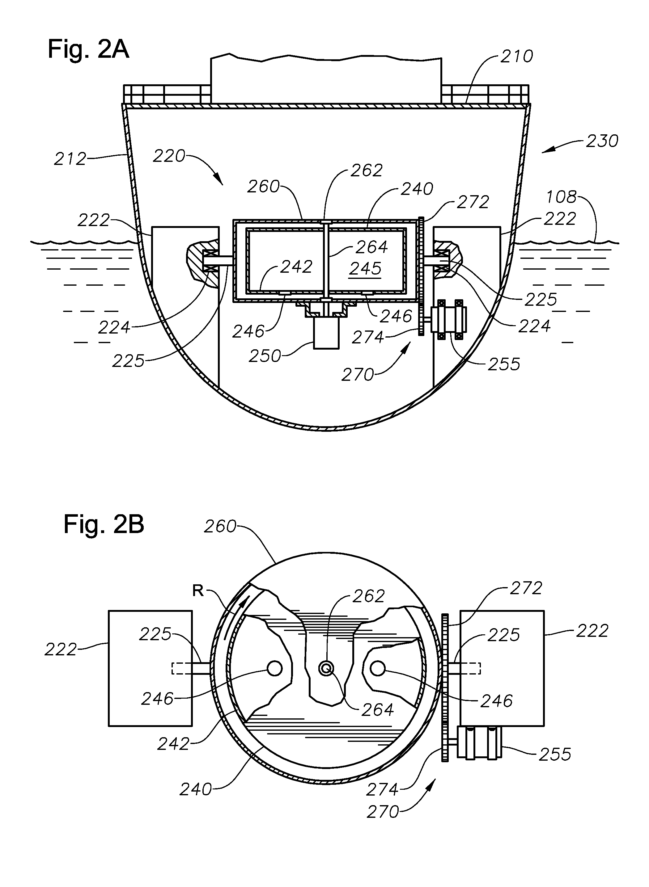
First, FIG. 2A provides a cross-sectional view of an intervention vessel 230 having a water-agitating mechanism, in a The intervention vessel 230 includes a deck 210 and a hull 212. The water-agitating mechanism is shown within the hull 212 of the vessel 230 at 220.

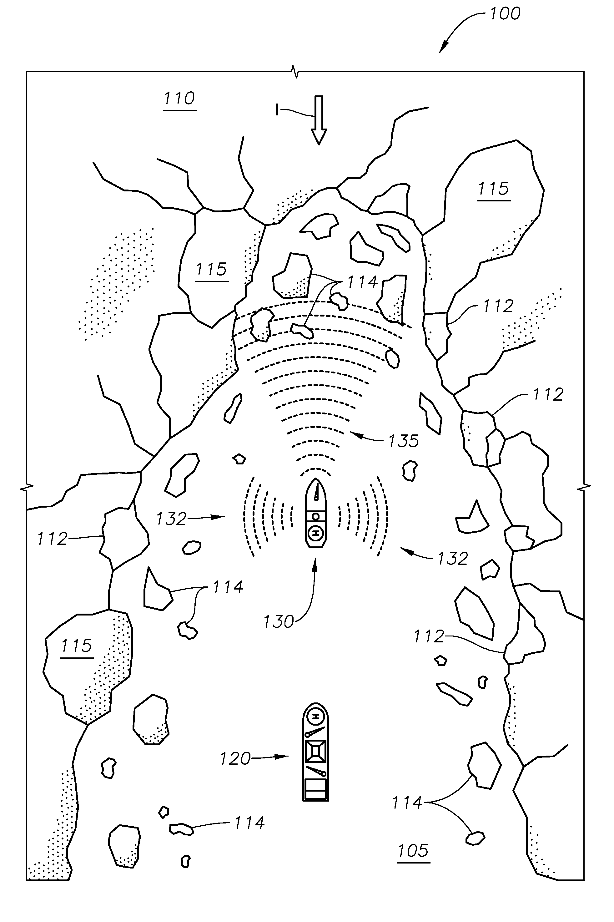
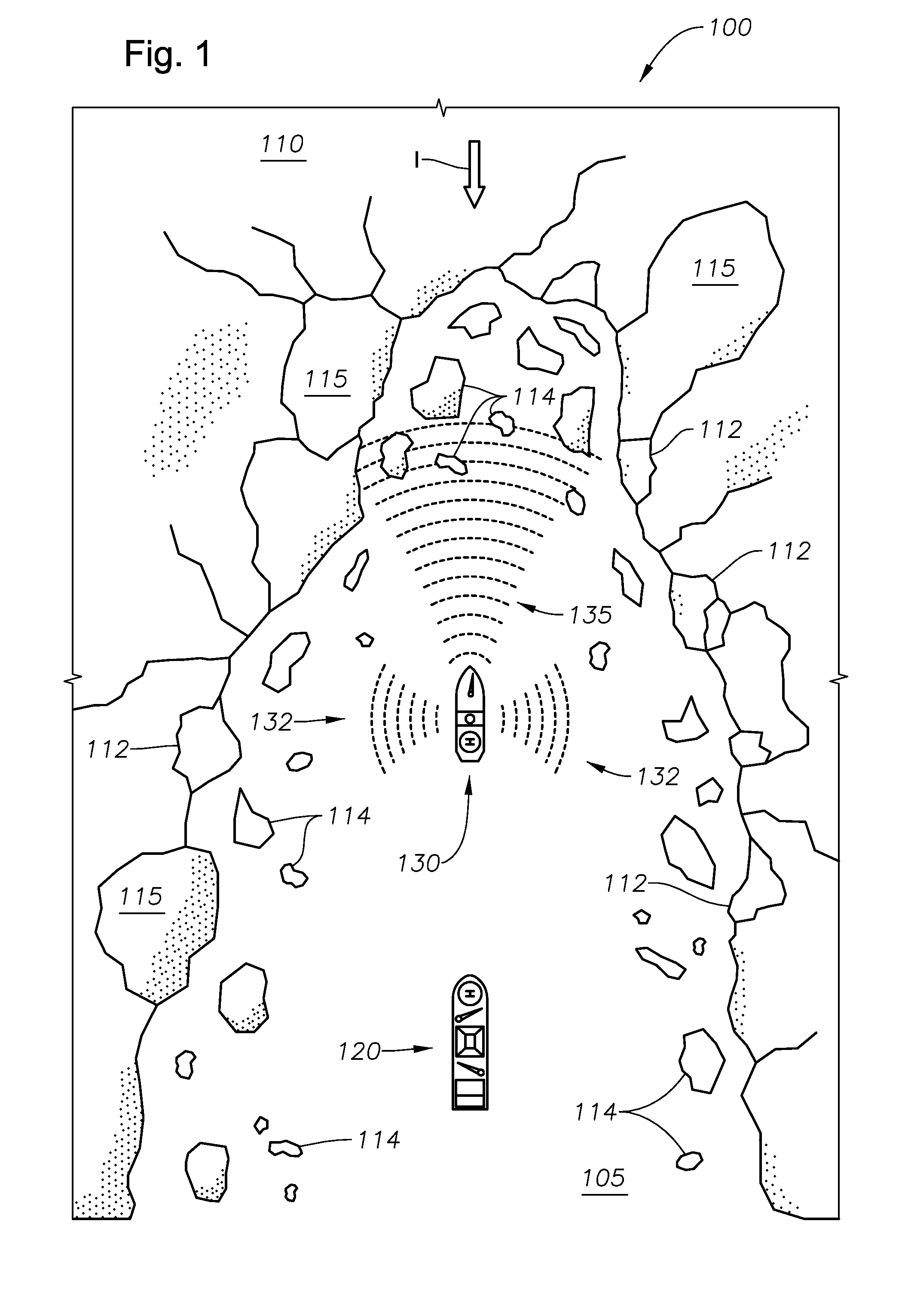
The vessel 230 is representative of the intervention vessel 130 of FIG. 1. In this respect, the vessel 230 is a ship-shaped vessel preferably having ice-breaking capabilities. In addition, the vessel 230 preferably has a large water displacement for generating substantial surface waves 135 during motion.

In the arrangement of FIG. 2, the water-agitating mechanism 230 is a gryoscopic system. Gyroscopes are commonly used in modern marine structures for providing stability to vessels deployed on the high seas. Stabilization increases passenger comfort and safety, reduces wear and tear on equipment, and increases the accuracy of warship artillery.

A gryoscopic system uses angular momentum and precession to counter ship oscilla...

second embodiment

FIG. 3 is a side view of an intervention vessel 330 using a water-agitating mechanism 320 in a The intervention vessel 330 includes a deck 310 and a hull 312. The vessel 330 is representative of the intervention vessel 130 of FIG. 1. In this respect, the vessel 330 is a ship-shaped vessel preferably having ice-breaking capabilities. However, it is understood that the vessel 330 may be of any shape. For example, a non-ship-shaped vessel such as an offshore working platform may utilize the water-agitating mechanism 320.

In the vessel 330 of FIG. 3, the water-agitating mechanism 320 comprises a plurality of pneumatic guns 322. The pneumatic guns 322 are suspended from cables 324. The cables 324, in turn, are supported by cable rods 326 extending laterally from the vessel 330. The pneumatic guns 322 extend into the marine body 105. Alternatively, in some embodiments the pneumatic guns 322 may be extended or towed behind the vessel.

The pneumatic guns 322 are preferably large-diameter, cy...

third embodiment

FIG. 4 is a cross-sectional view of an intervention vessel 430 using a water-agitating mechanism 420 in a The intervention vessel 430 includes a deck 410 and a hull 412. The vessel 430 is again representative of the intervention vessel 130 of FIG. 1. In this respect, the vessel 430 is a ship-shaped vessel preferably having ice-breaking capabilities. However, it is understood that the vessel 430 may be of any shape.

In the vessel 430 of FIG. 4, the water-agitating mechanism 420 comprises a plurality of paddles 422. The paddles 422 are supported by oars 424. The oars 424, in turn, are supported by a rotating shaft 426 that extends laterally from each side of the vessel 430.

In order to generate waves 135, the shaft 426 is rotated. Rotation may be clockwise, counter-clockwise, or intermittently clockwise and counter-clockwise. Rotation of the shaft 426 is driven by a motor assembly 440. The motor assembly 440 includes a motor 442. The motor 442 is supported by a stand or platform 446. T...


PUM


Abstract

A system and method for clearing an approaching floating ice mass comprising locating a hydrocarbon development platform in a marine environment, and determining a direction from which the ice mass is approaching the hydrocarbon development platform. The method also includes providing an intervention vessel having a water-agitating mechanism associated therewith for propagating artificially generated waves towards a leading edge of the approaching ice mass to fracture the ice mass along the leading edge, thereby causing small ice pieces to separate from the ice mass.

Description

BACKGROUND OF THE INVENTIONThis section is intended to introduce various aspects of the art, which may be associated with exemplary embodiments of the present disclosure. This discussion is believed to assist in providing a framework to facilitate a better understanding of particular aspects of the present disclosure. Accordingly, it should be understood that this section should be read in this light, and not necessarily as admissions of prior art.FIELD OF THE INVENTIONThe present invention relates to the field of offshore operations in Arctic conditions. More specifically, the present invention relates to the break-up of ice masses in Arctic waters to prevent a collision of such ice masses with an offshore operations facility.GENERAL DISCUSSION OF TECHNOLOGYAs the world's demand for fossil fuels increases, energy companies find themselves pursuing hydrocarbon resources in more remote areas of the world. Such pursuits sometimes take place in harsh, offshore conditions such as the No...

Claims


Application Information

Patent Timeline
Patent Type & Authority Applications(United States)
IPC IPC(8): E02B3/00B63B35/08
CPCE02B3/00B63B35/08B63B2211/06
Inventor NEDWED, TIMOTHY J.KAMINSKY, ROBERT D.RALSTON, TERRANCE D.
Owner EXXONMOBIL UPSTREAM RES CO
Why Eureka
Try Eureka