
Press fitting method for heat pipe and heat sink

Inactive Publication Date: 2011-08-11
CHEN SHYH MING
View PDF2 Cites 4 Cited by
  • Summary
  • Abstract
  • Description
  • Claims
  • Application Information

AI Technical Summary

Benefits of technology

[0005]Accordingly, the primary object of the present invention is to provide a fitting method for heat pipe and heat sink which is fast, effective, and economic so as to ensure the tight connection and well heat dissipation.
[0006]Through the method, the production of the assembly is fast, and the heat dissipation performance is also raised for the needs.

Problems solved by technology

Prior fitting of the heat pipe and the fins of the heat sink is through welding which is complicated method and also not friendly to environment.
The flowing melting intermediate is hard to control a well uniformity and gaps are sometimes happened so that the fitting between the fins and the heat pipe is hard to achieve.
Therefore, the method is not economic.
But the macromolecule glue will be solidified by time and result in gaps so that the heat dissipation will be effected.

Method used


Image

  • Press fitting method for heat pipe and heat sink
  • Press fitting method for heat pipe and heat sink
  • Press fitting method for heat pipe and heat sink

Examples


first embodiment

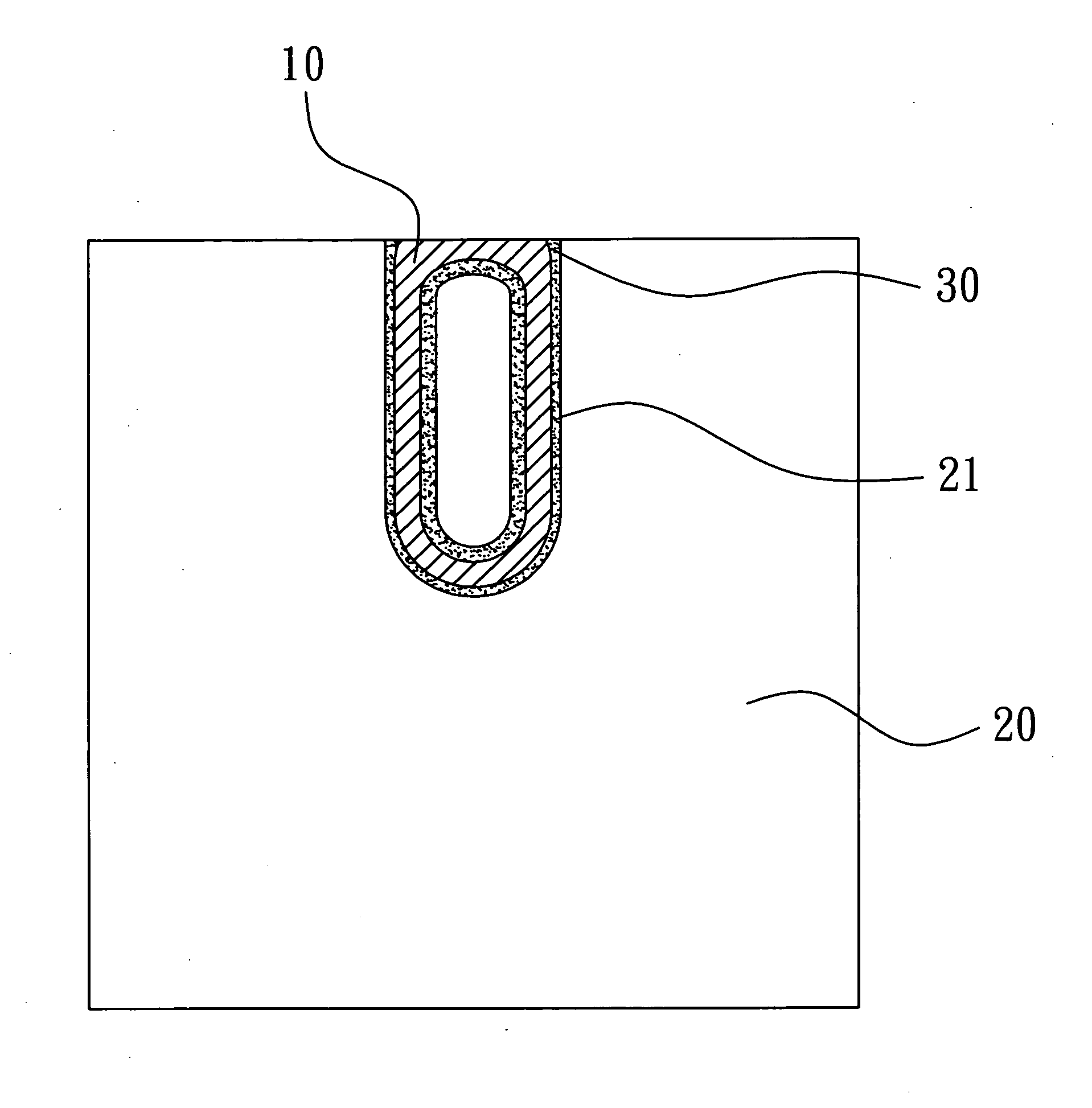
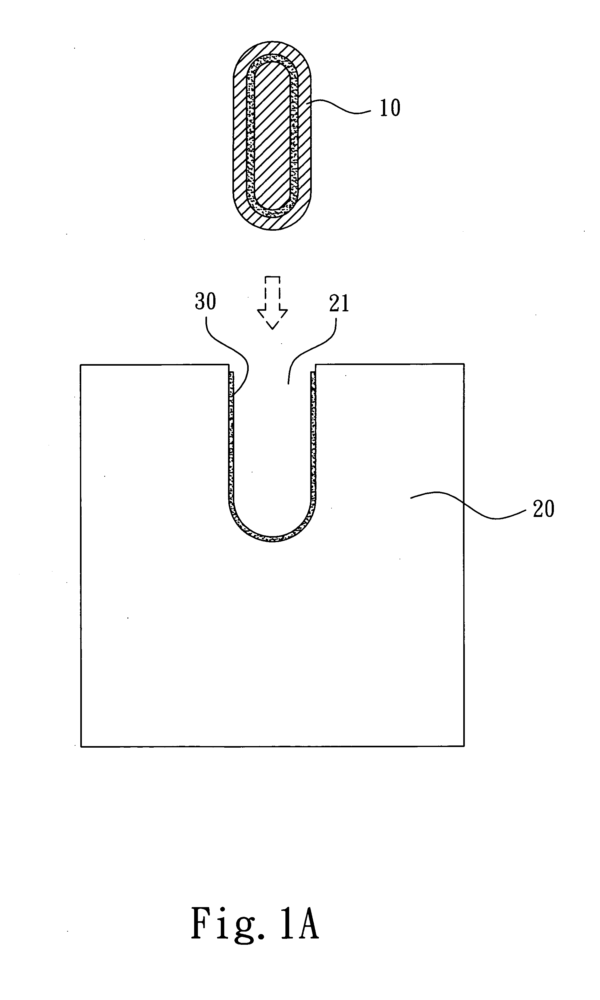
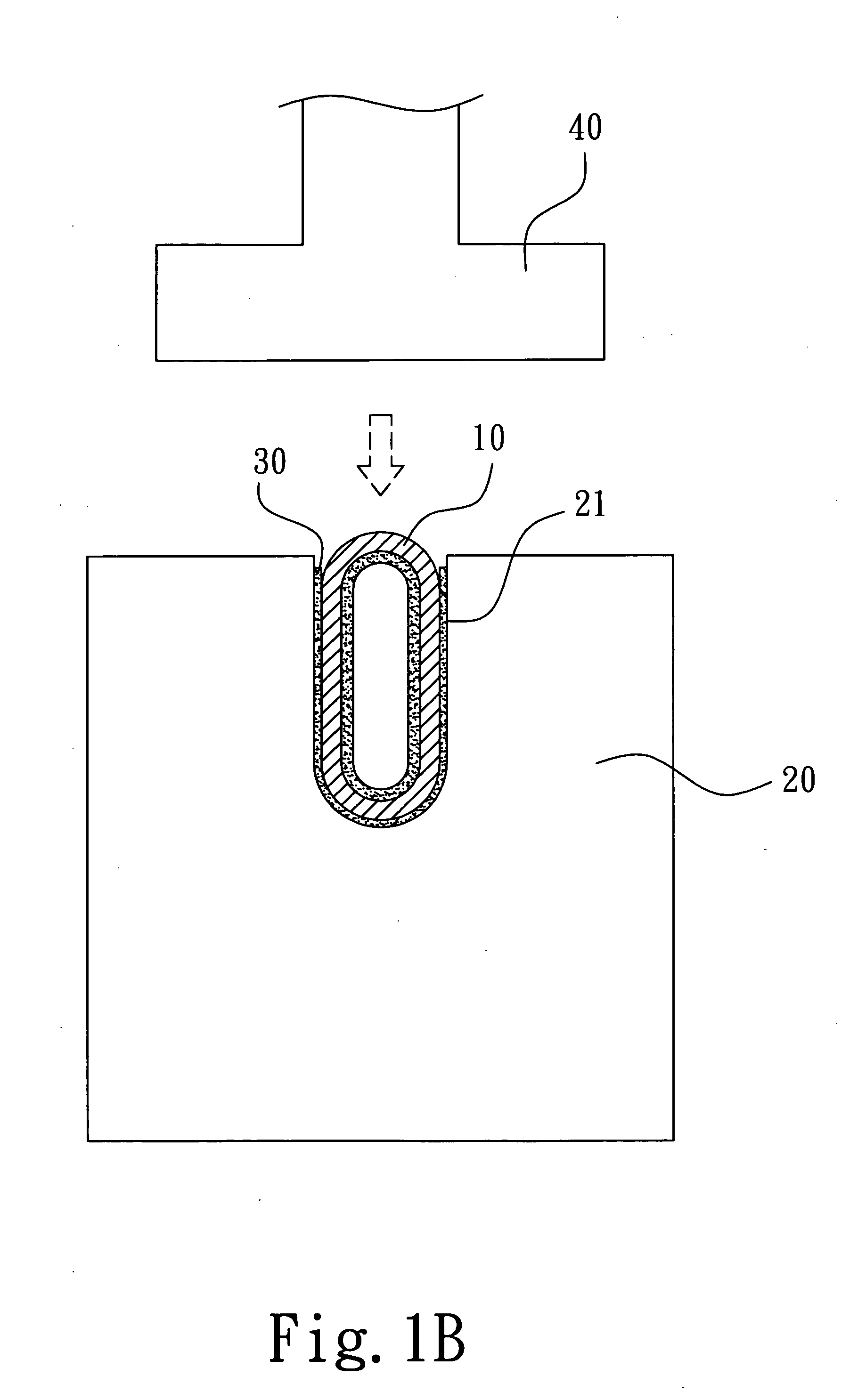
[0012]Referring to FIG. 1A to 1D, a press fitting method for heat pipe and heat sink according to the present invention is illustrated. The embodiment includes the following steps.

[0013]a) At least a heat pipe 10 and a heat sink 20 conducting heat to the heat pipe 10 are provided. The heat pipe 10 is approximately oval-shaped. The heat sink 20 is one of a plate, base, or fin module capable of conducting heat. The heat sink 20 has a groove 21 for receiving the heat pipe 10 on a side thereof. The heat pipe 10 will be protruded from a surface of the heat sink 20 while being received by the groove 21.

[0014]b) The heat pipe 10 is placed into the groove 21. A conductivity medium 30 is smeared around the junction of the heat pipe 10 and the heat sink 20.

[0015]c) The end of the heat pipe 10 protruded from the groove 21 is pressed by a press mold 40 so as to be deformed and fit to the groove 21 as one. (shown in FIG. 1D)

[0016]Through the above steps, the heat pipe 10 is tightly fitting to th...

second embodiment

[0018]The difference between the two embodiments is that a heat pipe 10a of the second embodiment is below (or level with) the surface of the heat sink 20 while being received by the groove 21 of the heat sink 20. The heat pipe 10a is placed into the groove 21. The conductivity medium 30 is smeared to the junction of the heat pipe 10a and the heat sink 20. A press mold 40a has a protrusion for the heat pipe 10a inside the groove 21. An end of the heat pipe 10a pointing out the groove will be pressed by the protrusion of the press mold 40a so as to be deformed and fit to the groove 21.

third embodiment

[0019]Referring to FIG. 3A to 3E, press fitting method for heat pipe and heat sink according to the present invention is illustrated. The embodiment includes the following steps.

[0020]a) At least one heat pipe 50 and a heat sink 60 conducting heat to the heat pipe 50 are provided. The heat pipe 50 is approximately oval-shaped. The heat sink 60 has a plurality of fin 61. The plurality of fin 61 has a through hole 62 for receiving the heat pipe 50.

[0021]b) The heat pipe 50 is placed into the through hole 62. A conductivity medium 70 is smeared to the junction of the heat pipe 50 and the through hole 62. A jig 80 passing through the fins is holding against one side of the heat pipe 50.

[0022]c) Another side of the heat pipe 50 against the jig 80 is pressed by a press mold 82. The heat pipe 50 being pressed is deformed towards the fins 61 so that the fins 61 and the heat pipe 50 will be tightly fit together (as shown in FIGS. 3D and 3E).

[0023]Referring to FIGS. 4A to 4D, the fourth embod...


PUM

PropertyMeasurementUnit
Electrical conductivityaaaaaaaaaa
Shapeaaaaaaaaaa
Heataaaaaaaaaa

Abstract

A press fitting method for heat pipe and heat sink includes the following steps. a) At least a heat pipe and a heat sink conducting heat to the heat pipe are provided. The heat sink is one of a heat conducting plate or a fin module. The heat sink has a groove for receiving the heat pipe. b) The heat pipe is placed into the groove. c) An end of the heat pipe or the heat pipe under the fins is pressed by a press mold so as to be deformed and fit to the groove as one. Through the above steps, an efficient and quick method is provided and the heat pipe will be tightly fitted to the heat sink so as to achieve a better heat dissipation.

Description

FIELD OF THE INVENTION[0001]The present invention relates to a press fitting method for heat pipe and heat sink, and particular to a press fitting method applied to computer, electronic or LED lamp device or related heat dissipating technology.DESCRIPTION OF THE PRIOR ART[0002]Heat pipe with heat sink are commonly used for the purpose of providing a better heat dissipation to a computer, electronic or LED lamp device. The heat sink is usually a heat conducting plate (base) or a fin module. The heat sink is attached to a heat source so that the heat will be quickly dissipated through the heat pipe connected to the heat sink.[0003]Prior fitting of the heat pipe and the fins of the heat sink is through welding which is complicated method and also not friendly to environment. Each fin needs to be welded with heated intermediate. The flowing melting intermediate is hard to control a well uniformity and gaps are sometimes happened so that the fitting between the fins and the heat pipe is ...

Claims


Application Information

Patent Timeline
IPC IPC(8): B21D53/02
CPCB21C37/24Y10T29/4935B21K23/00B21K25/00B23P11/00B23P2700/09B23P2700/10F28D15/0233F28D15/0275F28F1/12H01L21/4882H01L23/427H01L2924/0002B21D53/08H01L2924/00F28F2275/10F28F2275/12
Inventor CHEN, SHYH-MING
Owner CHEN SHYH MING
Learn More