
Multi-layered ballistics armor

a multi-layer, ballistic armor technology, applied in the field of ballistic armor, can solve the problems that the effectiveness of conventional ceramic armor can quickly deteriorate, and achieve the effects of improving protection against multiple ballistic impacts, and minimizing the fragmentation of armor

Active Publication Date: 2011-08-11
INT COMPOSITES TECH
View PDF33 Cites 30 Cited by
  • Summary
  • Abstract
  • Description
  • Claims
  • Application Information

AI Technical Summary

Benefits of technology

[0004]Briefly and in general terms, the present invention provides for a multi-layered ballistics armor stabilized to minimize fragmentation of the armor, to minimize deterioration of the armor when subjected to shock waves or shear forces of a ballistic impact, to provide improved protection against multiple ballistic impacts.
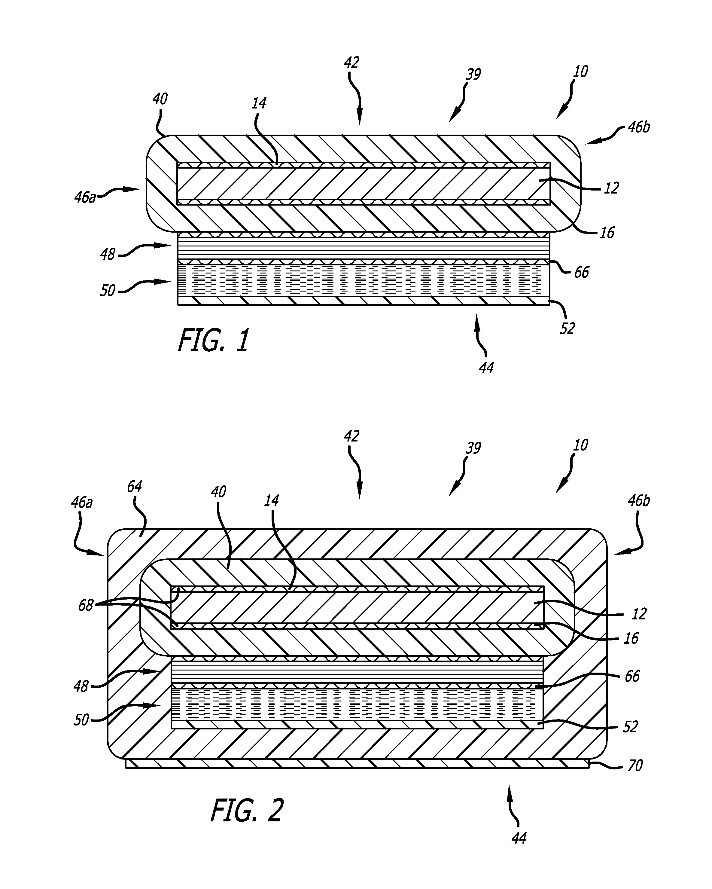
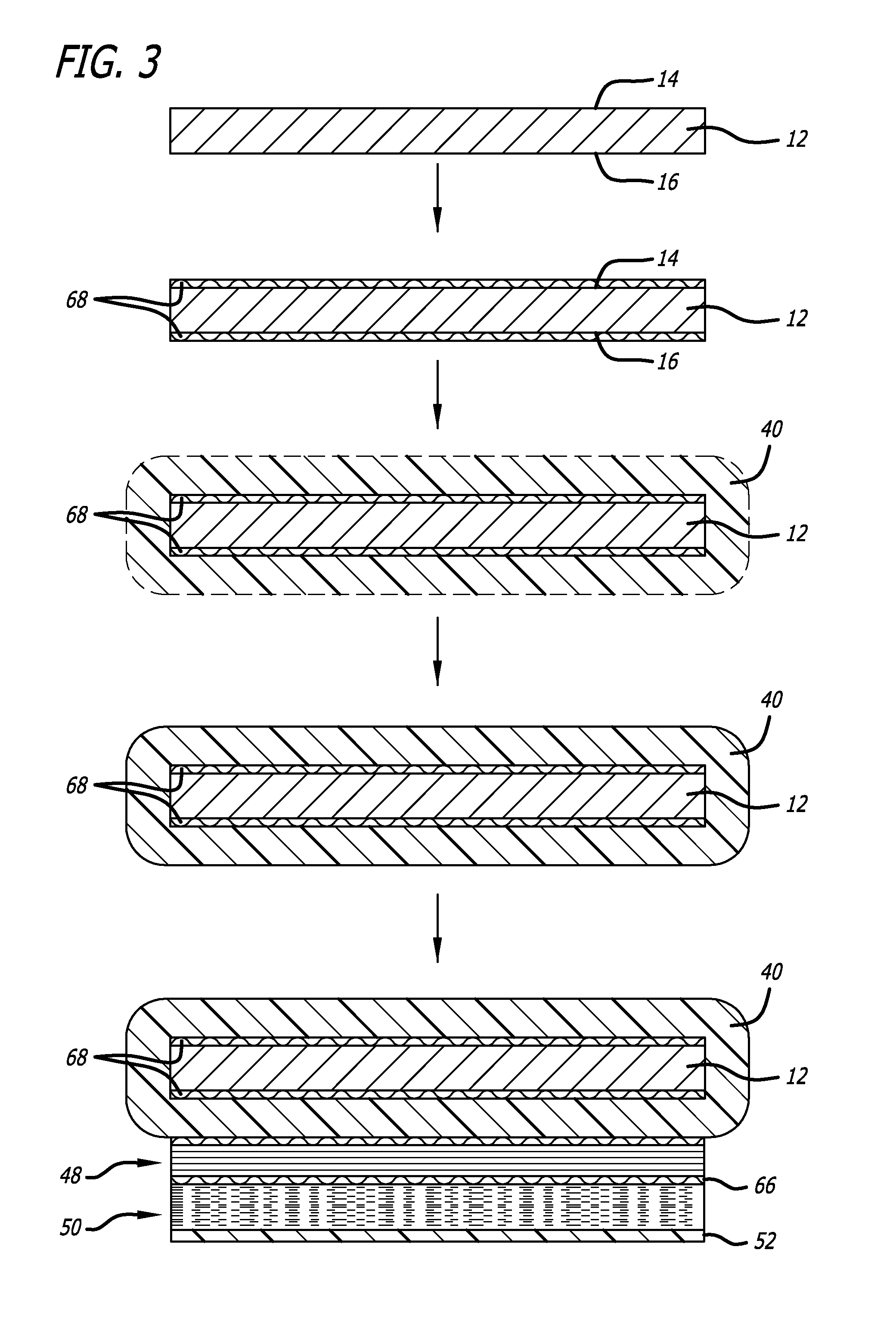
[0010]The present invention also provides for a method of manufacturing multi-layered armor stabilized to minimize fragmentation of the armor, by providing an impact absorbing layer and one or more primary containment envelopes covering at least a portion of the impact absorbing layer. The one or more primary containment envelopes preferably are provided over at least the strike face or front impact receiving side and a rear side of the impact absorbing layer, to minimize and contain fragmentation of the impact absorbing layer. One or more adhesive layers also may optionally be provided coating at least one of the strike face or front impact receiving side and the rear side of the impact absorbing layer. In a presently preferred aspect, the one or more primary containment envelopes can be formed by placing a containment resin matrix around the impact absorbing layer, such as by wrapping a fibrous material in a containment resin matrix around the impact absorbing layer, and allowing the containment resin matrix to cure. One or more composite backing layers may also be provided over the one or more primary containment envelopes, and can include an energy absorbing layer, an outer flame resistant layer, and a standoff spacer layer.
[0011]The secondary containment envelope can be provided over at least a portion of the one or more primary containment envelopes, such as over at least a front side and a rear side of the impact absorbing layer to minimize and contain fragmentation of the impact absorbing layer. An adhesive layer may be provided over one or both of the strike face or front impact receiving side and the rear side of the impact absorbing layer. One or more composite backing layers can be also be placed over the rear side of the one or more primary containment envelopes, with an optional layer of adhesive between the rear side of the primary containment envelope and the one or more composite backing layers, which can include an energy absorbing layer, and a flame resistant layer. A ductile adhesive layer optionally may be placed between the energy absorbing layer and the one or more composite backing layer. The secondary containment envelope is preferably formed over at least a portion of the primary containment envelope, composite backing layer and energy absorbing layer, such as at least the front and rear sides of the primary containment envelope, composite backing layer and energy absorbing layer, such as by wrapping a fibrous material in a containment resin matrix around the impact absorbing layer, and allowing the containment resin matrix to cure. A flame resistant layer may also be formed over at least a portion of the secondary containment envelope. A standoff spacer layer defining one or more chambers or cells filled with a filler or air may also be provided opposing the strike face, between the secondary containment envelope and the substrate surface.

Problems solved by technology

However, it has been found that following an initial ballistic impact the effectiveness of conventional ceramic armor can quickly deteriorate significantly due to the inherent fragmentation of ceramic armor when subjected to shock waves or shear forces of a ballistic impact.

Method used


Image

  • Multi-layered ballistics armor
  • Multi-layered ballistics armor
  • Multi-layered ballistics armor

Examples


Embodiment Construction

[0033]While composite armor including a layer of ceramic between steel armor plates can be effective, there is a need to provide reduced weight composite armor, and it has been found that ceramic armor can quickly deteriorate significantly after a single ballistic impact to reduce the multiple impact protection of such ceramic based ballistics armor.

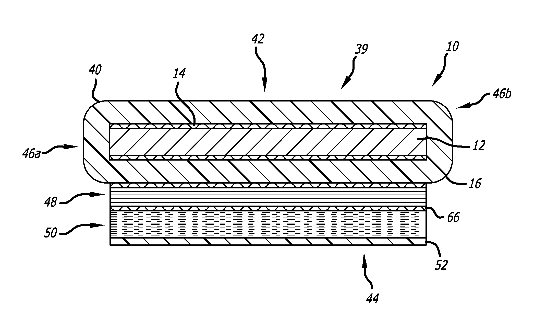
[0034]Accordingly, as is illustrated in the drawings, which are provided by way of example and not by way of limitation, the present invention provides for a multi-layered armor 10 stabilized to protect against fragmentation of the armor. The multi-layered armor includes an impact absorbing layer 12 having a strike face or front impact receiving side 14 and a rear side 16, so that a projectile received by the multi-layered armor proceeds from the front impact receiving side in a rearward direction toward the rear side. The multi-layered armor is preferably formed of a fragmenting material that is subject to fragmentation, spalling and sp...


PUM

PropertyMeasurementUnit
Forceaaaaaaaaaa
Electrical resistanceaaaaaaaaaa
Molecular weightaaaaaaaaaa

Abstract

The multi-layered ballistics armor includes one or more containment layers covering at least a portion of an impact absorbing layer formed of a fragmenting material to minimize and contain fragmentation of the impact absorbing layer. The one or more containment layers may include one or more primary containment envelopes, and the fragmenting material may be a ceramic such as silicon carbide, carbon / carbon composites, carbon / carbon / silicon carbide composites, boron carbide, aluminum oxide, silicon carbide particulate / aluminum metal matrix composites, or combinations thereof. The multi-layered armor may include one or more adhesive layers over the impact absorbing layer, one or more composite backing layers, an energy absorbing layer, and a flame resistant layer. A secondary containment envelope can be provided over the one or more primary containment envelopes, composite backing layers, and energy absorbing layer.

Description

BACKGROUND OF THE INVENTION[0001]The present invention is relates generally to ballistic armor, and more particularly relates to a composite multi-layered ballistic armor stabilized to protect against fragmentation of the armor to provide improved protection against armor-piercing projectiles.[0002]Conventional composite ballistic armor typically includes layers of different materials, and are commonly useful as armor for military vehicles. One advantage of such composite ballistic armor over all metal armor is that composite ballistic armor typically weighs less than metal armor of equivalent effectiveness, but so that composite armor can be stronger, lighter and less voluminous than traditional armor, but composite ballistic armor can also be designed to provide protection against armor-piercing projectiles such as high explosive anti-tank rounds.[0003]One common type of modern composite armor includes a layer of ceramic between steel armor plates, which has proved to be effective...

Claims


Application Information

Patent Timeline
IPC IPC(8): F41H5/04
CPCF41H5/0435F41H5/0457
Inventor FINGERHUT, RICHARD L.
Owner INT COMPOSITES TECH
Learn More