Mobile crane having counterweight

a mobile crane and counterweight technology, applied in the direction of cranes, etc., can solve the problems of hindering the counterweight from functioning as a weight, hindering the traveling movement of the mobile crane, and hindering the slewing movemen

Active Publication Date: 2011-08-11
KOBELCO CONSTR MASCH CO LTD
View PDF5 Cites 18 Cited by
  • Summary
  • Abstract
  • Description
  • Claims
  • Application Information

AI Technical Summary

Benefits of technology

[0013]According to this mobile crane, the counterweight-lifting cylinder can vertically push up the counterweight while receiving a reaction force from a ground surface against the gravity acting on the counterweight, by supply of a hydraulic pressure into the head-side cylinder chamber of the counterweight-lifting cylinder which has a pressure receiving area greater than that of the rod-side cylinder chamber. For this reason, the driving efficiency of the counterweight-lifting cylinder is higher than that of a cylinder required to be retracted to pull up a counterweight against a gravity acting thereon, i.e., a cylinder in which a hydraulic pressure is supplied into a rod-side cylinder chamber having a relatively small pressure receiving area to pull up the counterweight, such as the cylinders 160 and 260 shown in FIGS. 7 and 8. This makes it possible to lift the counterweight with a limited hydraulic pressure for the operation of the hydraulic cylinder and a limited diameter of the hydraulic cylinder, thus enabling the counterweight to be lifted / lowered by use of a low-cost hydraulic cylinder.

Problems solved by technology

The raising and lowering movement of the mast, however, involves a vertical displacement of the mast point at the upper end of the mast, which causes the following problems.
When the mast is lowered to increase the hanging radius of the counterweight, the counterweight is displaced downwardly and landed on a ground surface, which hinders the counterweight from functioning as a weight, and further hinders a slewing movement of the upper slewing body and a traveling movement of the mobile crane.
On the other hand, when the mast is raised to reduce the hanging radius of the counterweight, the counterweight is lifted up from the ground surface: releasing a load in this state may cause the mobile crane to be inclined rearwardly.
The length adjustment of the counterweight guy line, however, requires a lot of time and effort.
However, the above technique, using the hydraulic cylinder 160 or hydraulic cylinder 260 to pull up the counterweight 50 by the retraction of the cylinder, lowers driving efficiency.
Either case requires a costly hydraulic cylinder.

Method used


Image

  • Mobile crane having counterweight
  • Mobile crane having counterweight
  • Mobile crane having counterweight

Examples


Embodiment Construction

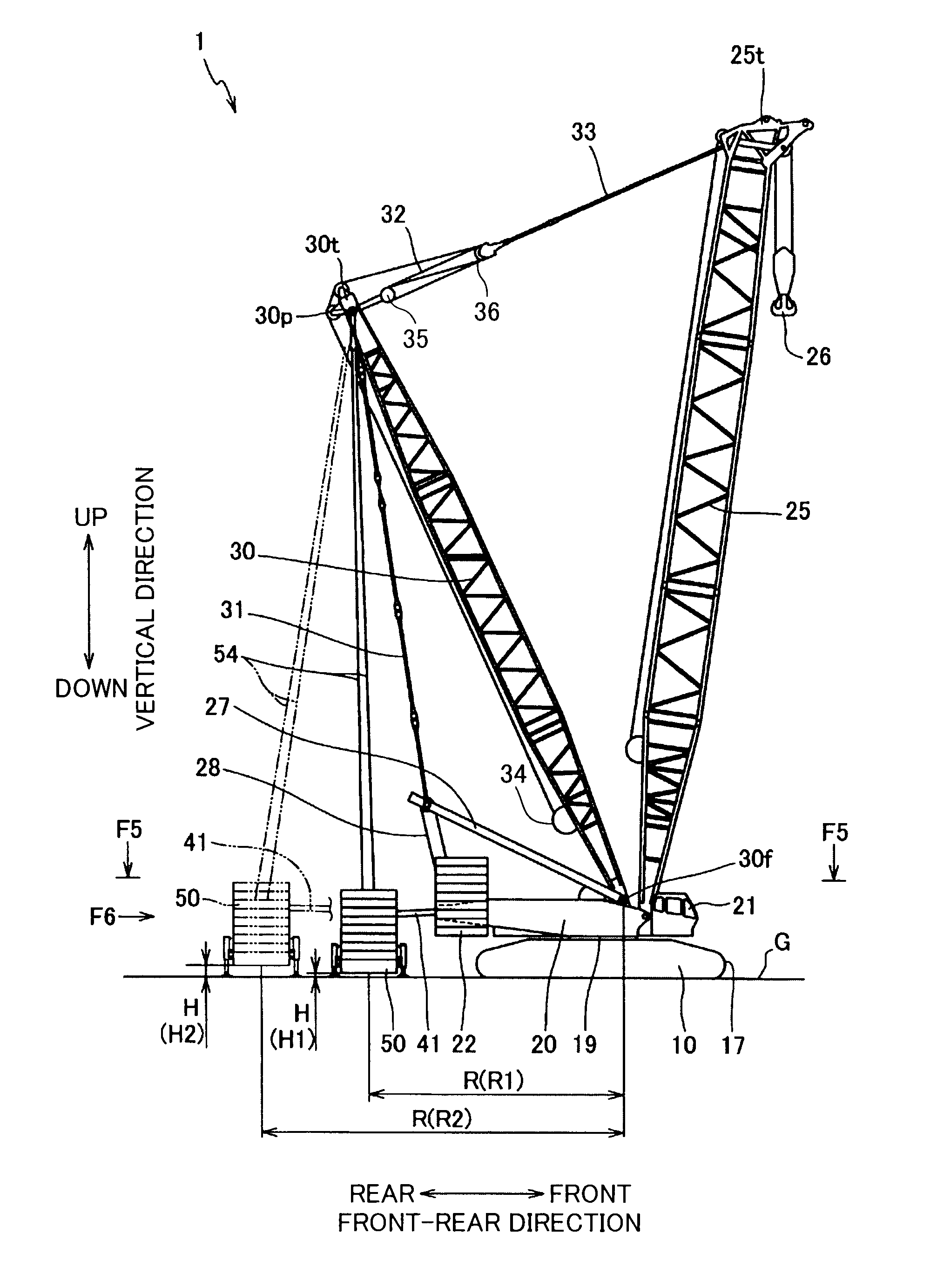
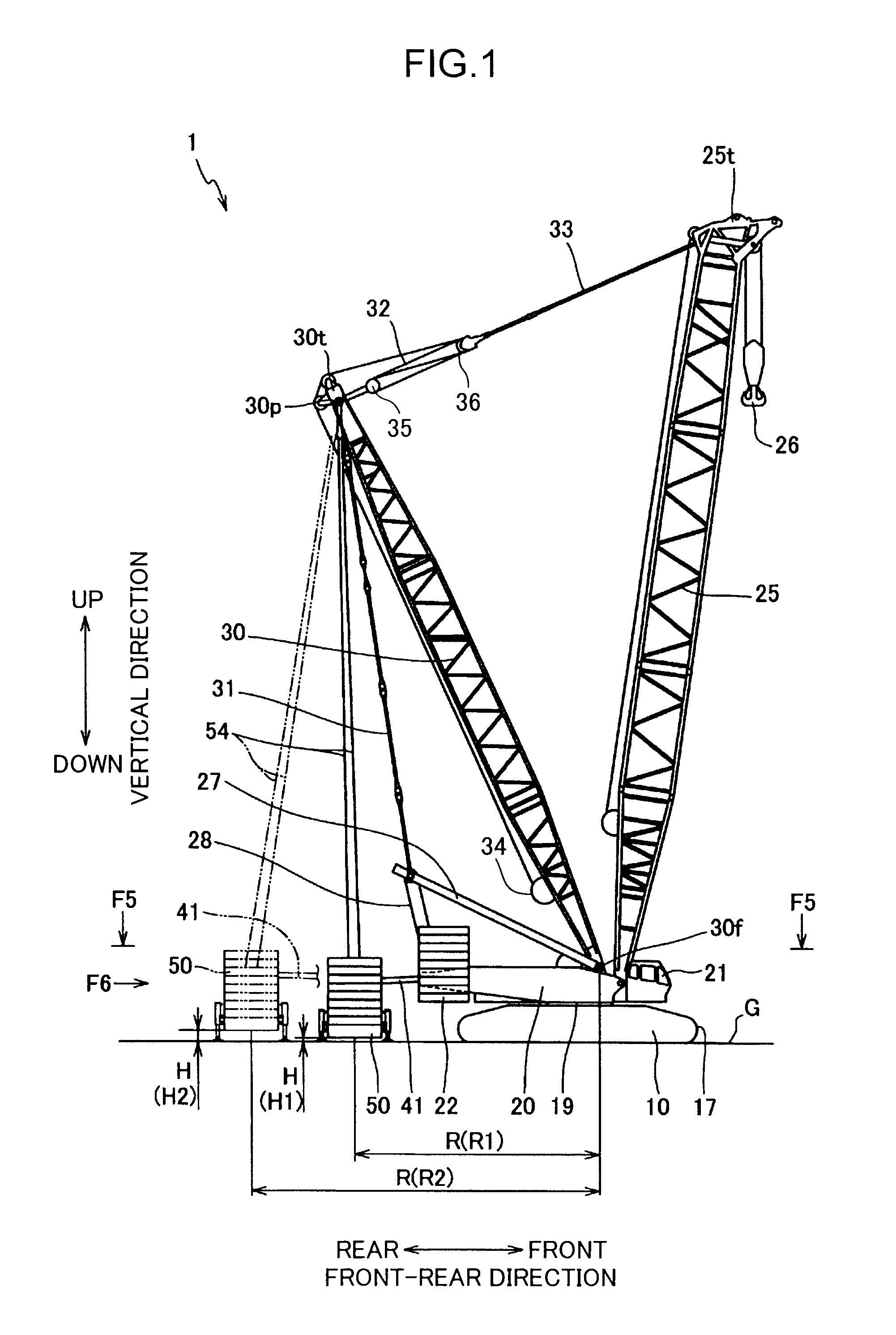
[0023]With reference to FIGS. 1 to 6, one embodiment of the present invention will now be described.

[0024]FIG. 1 shows a mobile crane 1. This mobile crane 1 is a counterbalance type crane, having not only upper slewing body-rear end counterweights 22, which are one attached to an rear end of the upper slewing body 20, but also a counterweight 50 (extra counterweight) disposed at the rear of an after-mentioned upper slewing body 20. Specifically, the mobile crane 1 comprises a lower propelling body 10, a upper slewing body 20 slewably mounted on the lower propelling body 10, a boom 25 pivotably attached to the upper slewing body 20, a mast 30 pivotably attached to the upper slewing body 20 at a position rearward of the boom 25, and a pair of right and left counterweight support members 41 attached to a rear end of the upper slewing body 20, the counterweight 50 being hung from the upper end of the mast 30. Furthermore, as shown in FIG. 4A, attached to the counterweight 50 are a plura...


PUM


Abstract

Provided is a mobile crane capable of adjusting a counterweight height with no use of a costly hydraulic cylinder. The mobile crane comprises a lower propelling body, a upper slewing body, a boom pivotably attached to the upper slewing body, a mast which is at the rear of the boom and adapted to be raised and lowered so as to raise and lower the boom, a counterweight which is at the rear of the upper slewing body and hung from the mast through a guy line, and a counterweight-lifting cylinder attached to the counterweight so as to be extended to vertically push up the counterweight with respect to a ground surface. The counterweight-lifting cylinder has a cylinder body, a piston partitioning an internal space of the cylinder body into an upper head-side cylinder chamber and a lower rod-side cylinder chamber, and a rod extending from the piston downwardly beyond an lower end of the cylinder body. the counterweight-lifting cylinder is extended by supply of a hydraulic pressure into the head-side cylinder chamber and retracted by supply of a hydraulic pressure into the rod-side cylinder chamber.

Description

BACKGROUND OF THE INVENTION[0001]1. Field of the Invention[0002]The present invention relates to a mobile crane having a counterweight.[0003]2. Description of the Background Art[0004]Heretofore, there has been known a large mobile crane having a counterweight for increasing a lifting capacity. For example, JP 2008-297112 A discloses a mobile crane which comprises a lower propelling body, a upper slewing body adapted to be slewed on the lower propelling body, a lattice-structured mast attached to the upper slewing body, and a counterweight hung from an upper end of the mast through a guy line, at a position rearward of the upper slewing body. In this type of mobile crane, a crane lifting capacity is adjusted by changing a horizontal distance between a mast foot which is a supported point of a base end of the mast and a center of gravity of the counterweight (the horizontal distance will hereinafter be referred to as “hanging radius of the counterweight”), or changing a mass of the co...

Claims


Application Information

Patent Timeline
Patent Type & Authority Applications(United States)
IPC IPC(8): B66C23/76
CPCB66C23/76
Inventor KUROTSU, HITOSHI
Owner KOBELCO CONSTR MASCH CO LTD
Why Eureka
Try Eureka