
Control concept for limit-value management for dc/dc converter in an energy system

a technology of limit value management and converter, applied in the direction of battery/fuel cell control arrangement, safety/protection circuit, capacitor propulsion, etc., can solve the problems of reducing the maximum power which can be output to the electrical drive, the maximum power which can be output to the electrical component, and the limit is accordingly limited, so as to achieve a balanced power budget, the control of the power consumption cannot be solved, and the power consumption of the components can be reduced.

Active Publication Date: 2011-08-11
ROBERT BOSCH GMBH
View PDF6 Cites 10 Cited by
  • Summary
  • Abstract
  • Description
  • Claims
  • Application Information

AI Technical Summary

Benefits of technology

[0003]The object of the present invention is to increase the availability of the electrical component in order in this way to ensure optimum operational availability of the electrical component, and to protect the DC / DC converter against damage.

Problems solved by technology

The maximum power which can be output to the electrical component, which may be an electrical drive for a motor vehicle, is accordingly limited by the power limit of the DC / DC converter.
Further additional electrical components connected to the DC / DC converter, such as electrical loads, reduce the maximum power which can be output to the electrical drive.
Furthermore, it is possible that a power demand to the electrical component above the power limit of the DC / DC converter could result in the latter being damaged.

Method used


Image

  • Control concept for limit-value management for dc/dc converter in an energy system
  • Control concept for limit-value management for dc/dc converter in an energy system
  • Control concept for limit-value management for dc/dc converter in an energy system

Examples


Embodiment Construction

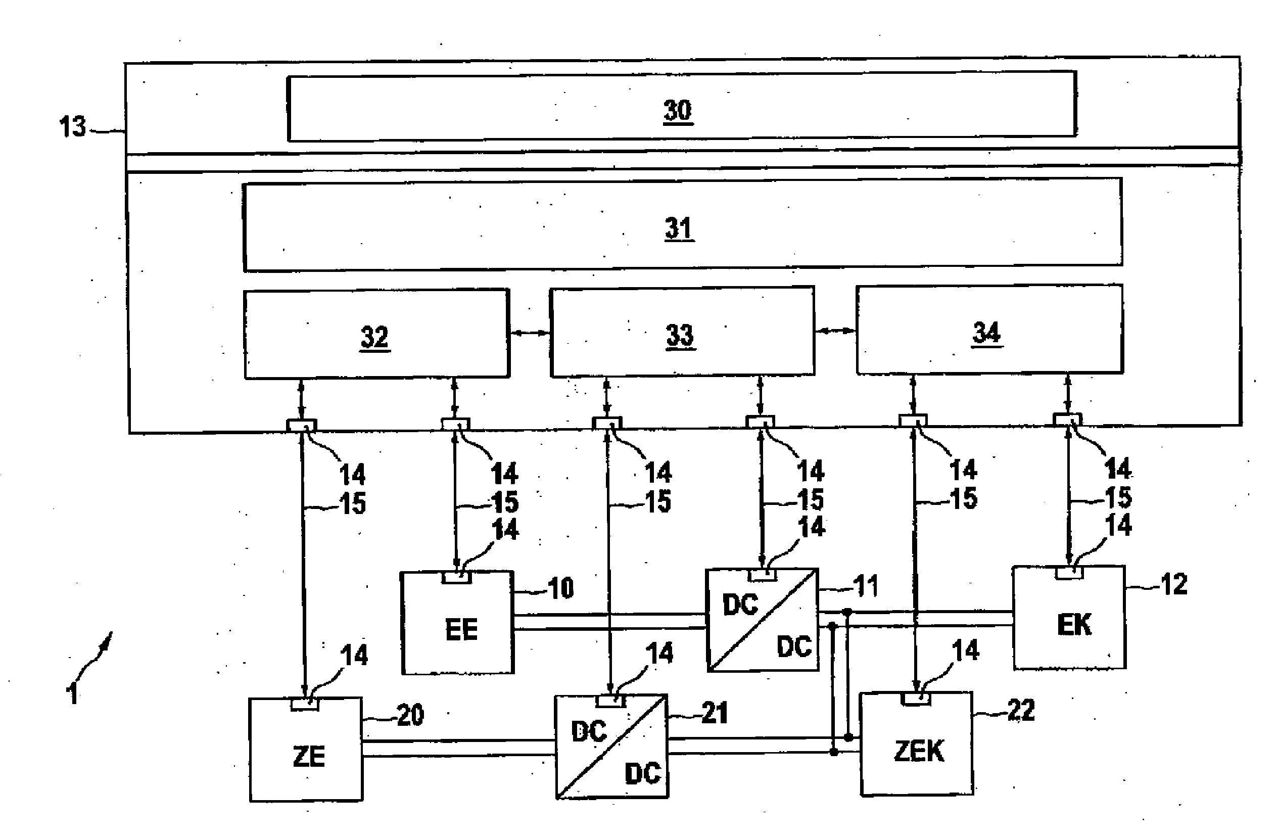
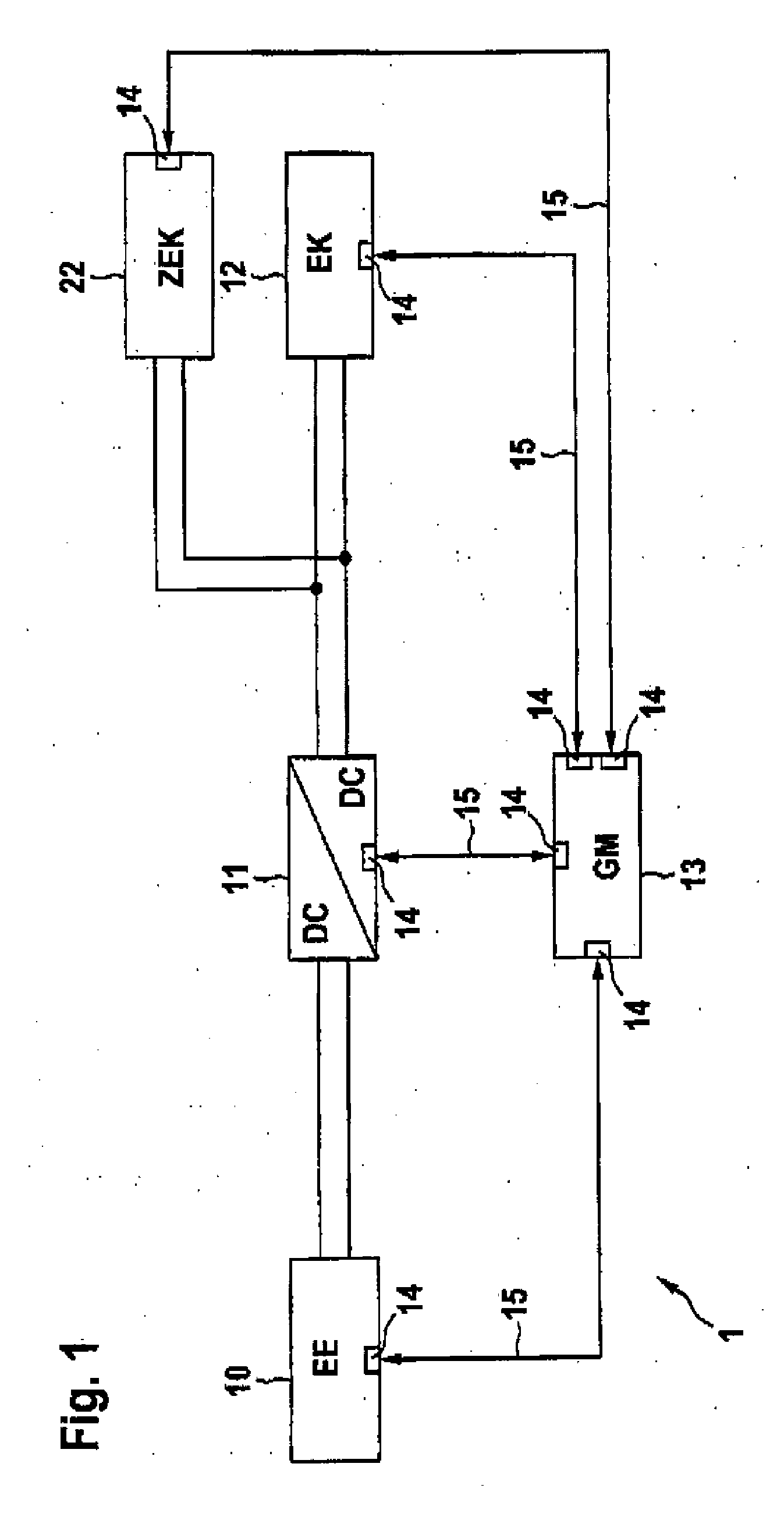
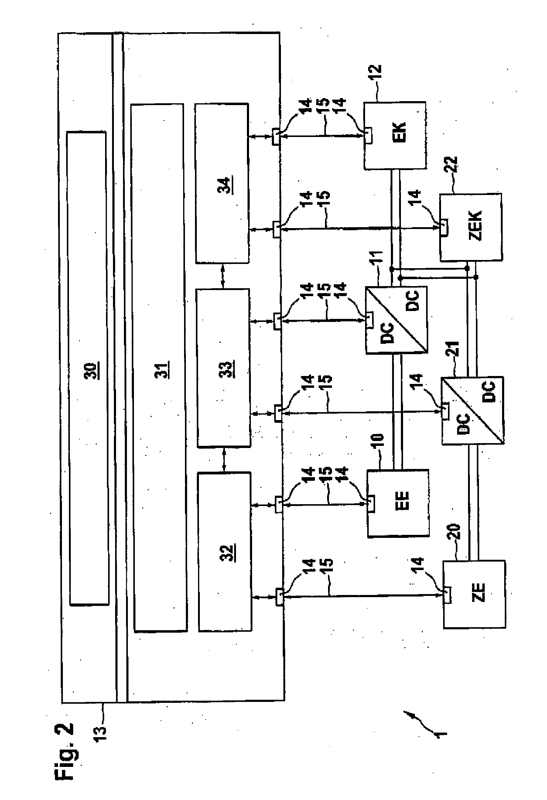
[0017]FIG. 1 schematically illustrates an energy system 1 in which an energy unit 10 is electrically connected to a DC / DC converter 11. An electrical component 12 is arranged at the output of the DC / DC converter 11. A second electrical component 22 is connected in parallel at the output of the DC / DC converter 11. The energy unit 10 has an interface 14 which is coupled via an information channel 15 to an interface 14 of a limit-value management system 13. The DC / DC converter 11 is also connected by an interface 14, via an information channel 15, to the limit-value management system 13 via an interface 14. Furthermore, the electrical component 12, which likewise has an interface 14, and the second electrical component 22, which also has an interface 14, are connected to one another by means of the limit-value management system 13 via a respective interface 14. Signals can be interchanged via the information channels 15 between the individual components, by means of the limit-value man...


PUM


Abstract

An apparatus for controlling an energy system having at least one energy unit and at least one DC / DC converter, wherein the DC / DC converter is coupled to at least one electrical component, and a power output to the electrical component can be controlled by the DC / DC converter, with the maximum power which can be output to the electrical component being determined by a power limit value of the DC / DC converter.The invention provides that the energy unit and the DC / DC converter and the electrical component are coupled via a limit-value management system which controls the power output such that, when power is demanded from the electrical component above the power limit value of the DC / DC converter, power is output up to the maximum power limit value.

Description

BACKGROUND OF THE INVENTION[0001]The invention relates to an apparatus for controlling an energy system having at least one energy unit and at least one DC / DC converter, wherein the DC / DC converter is coupled to at least one electrical component, and a power output to the electrical component can be controlled by the DC / DC converter, with the maximum power which can be output to the electrical component being determined by a power limit value of the DC / DC converter. The invention also relates to a method for controlling an energy system having at least one energy unit and at least one DC / DC converter, wherein the DC / DC converter is coupled to at least one electrical component, and a power output to the electrical component can be controlled by the DC / DC converter, with the maximum power which can be output to the electrical component being determined by a power limit value of the DC / DC converter.[0002]DE 102 23 117 A1 discloses energy systems being formed from a plurality of sub-com...

Claims


Application Information

Patent Timeline
Patent Type & Authority Applications(United States)
IPC IPC(8): H02J1/00
CPCB60L11/005Y02T90/34B60L11/1862B60L11/1887B60L11/1894B60L2210/10B60L2260/54H02J7/0029H02J7/0065H02J7/34H02M1/32Y02T10/7022Y02T10/7044Y02T10/705Y02T10/7216B60L11/1851B60L50/40B60L58/10B60L58/40B60L58/34H02J2207/20Y02T10/70Y02T10/72Y02T90/40
Inventor GLOHR, FRANCISSCHAEFERT, ARTHURSCHNEIDER, THOMAS
Owner ROBERT BOSCH GMBH
Learn More