Inverter-integrated electric compressor and assembly method therefor
- Summary
- Abstract
- Description
- Claims
- Application Information
AI Technical Summary
Benefits of technology
Problems solved by technology
Method used
Image
Examples
first embodiment
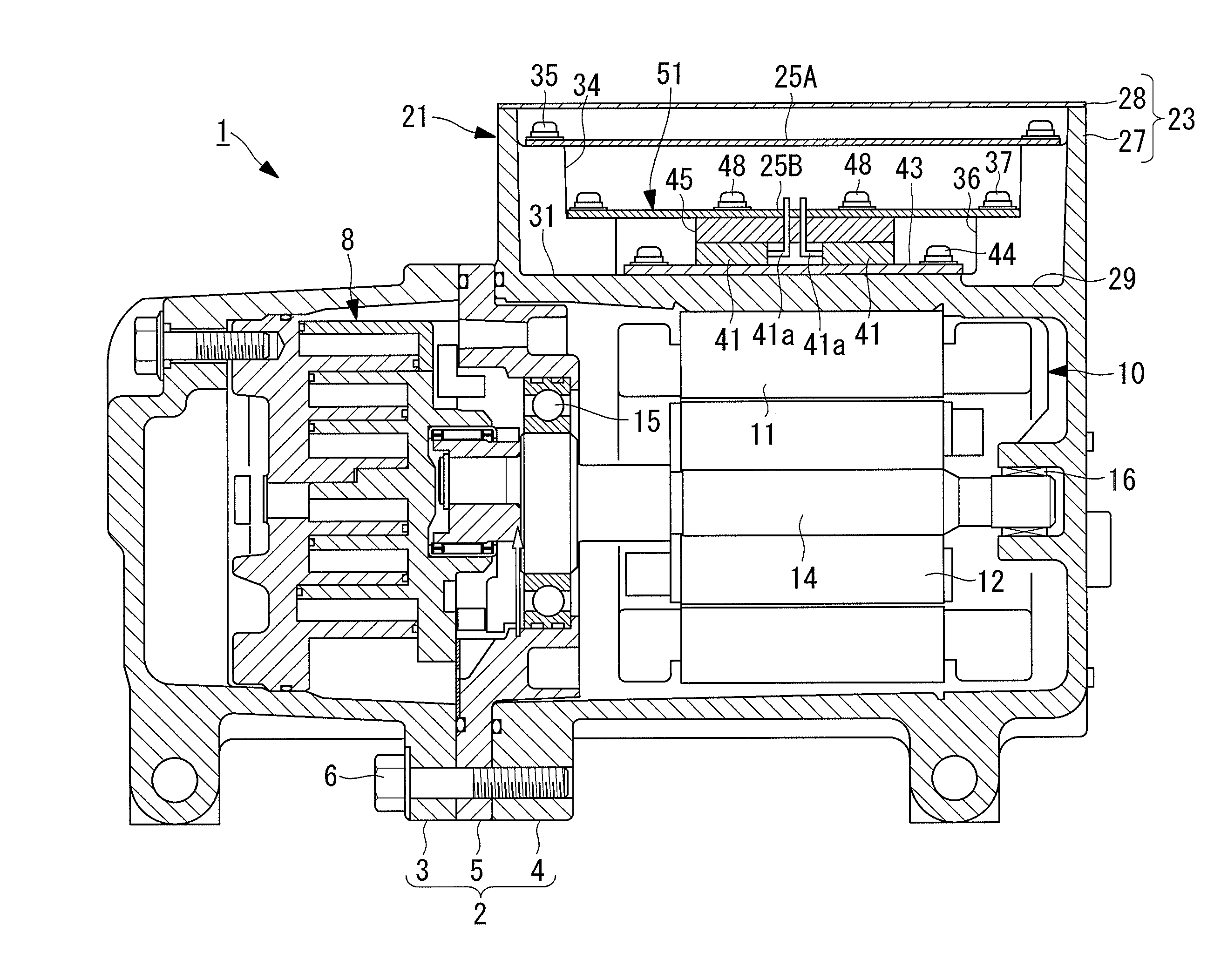
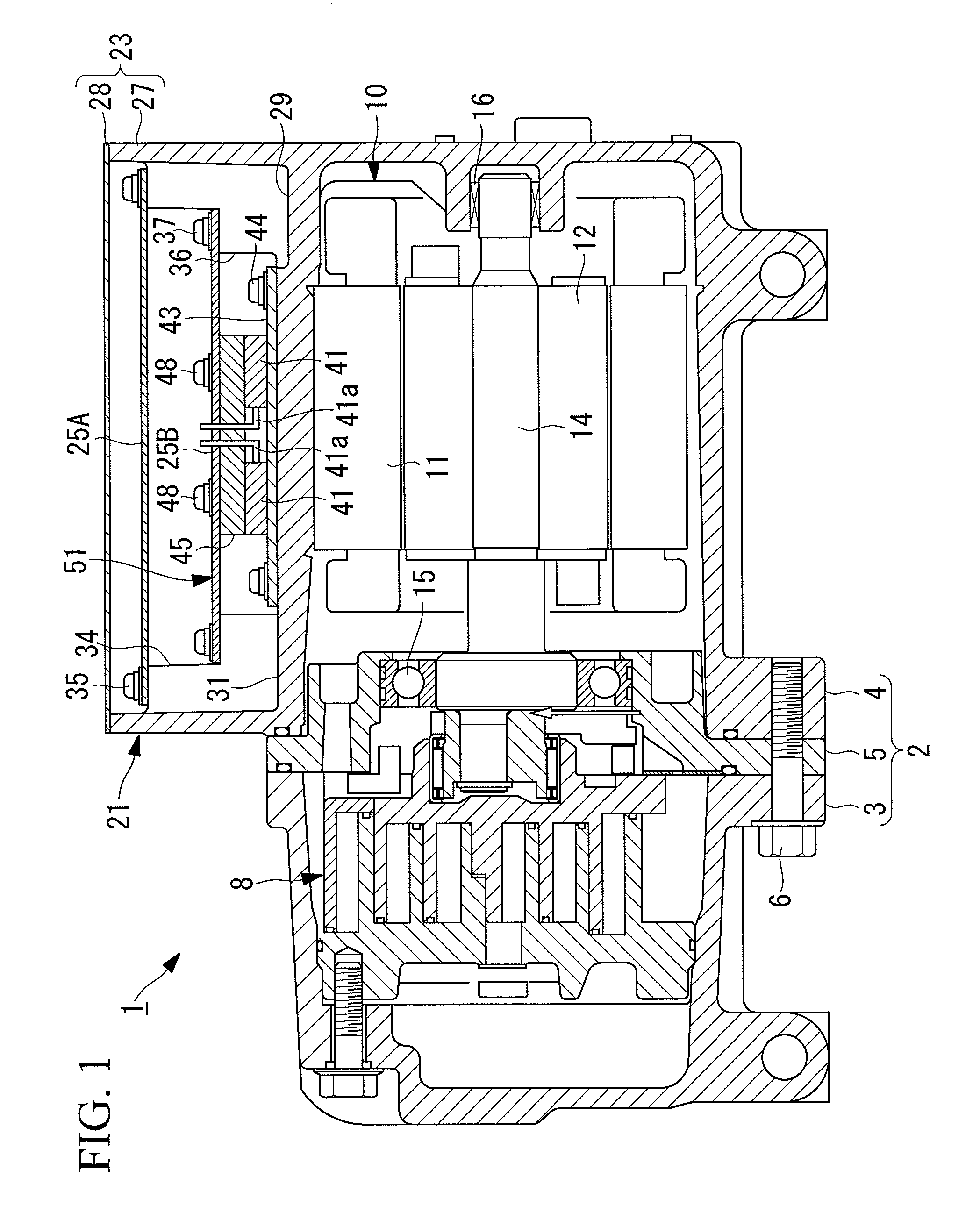
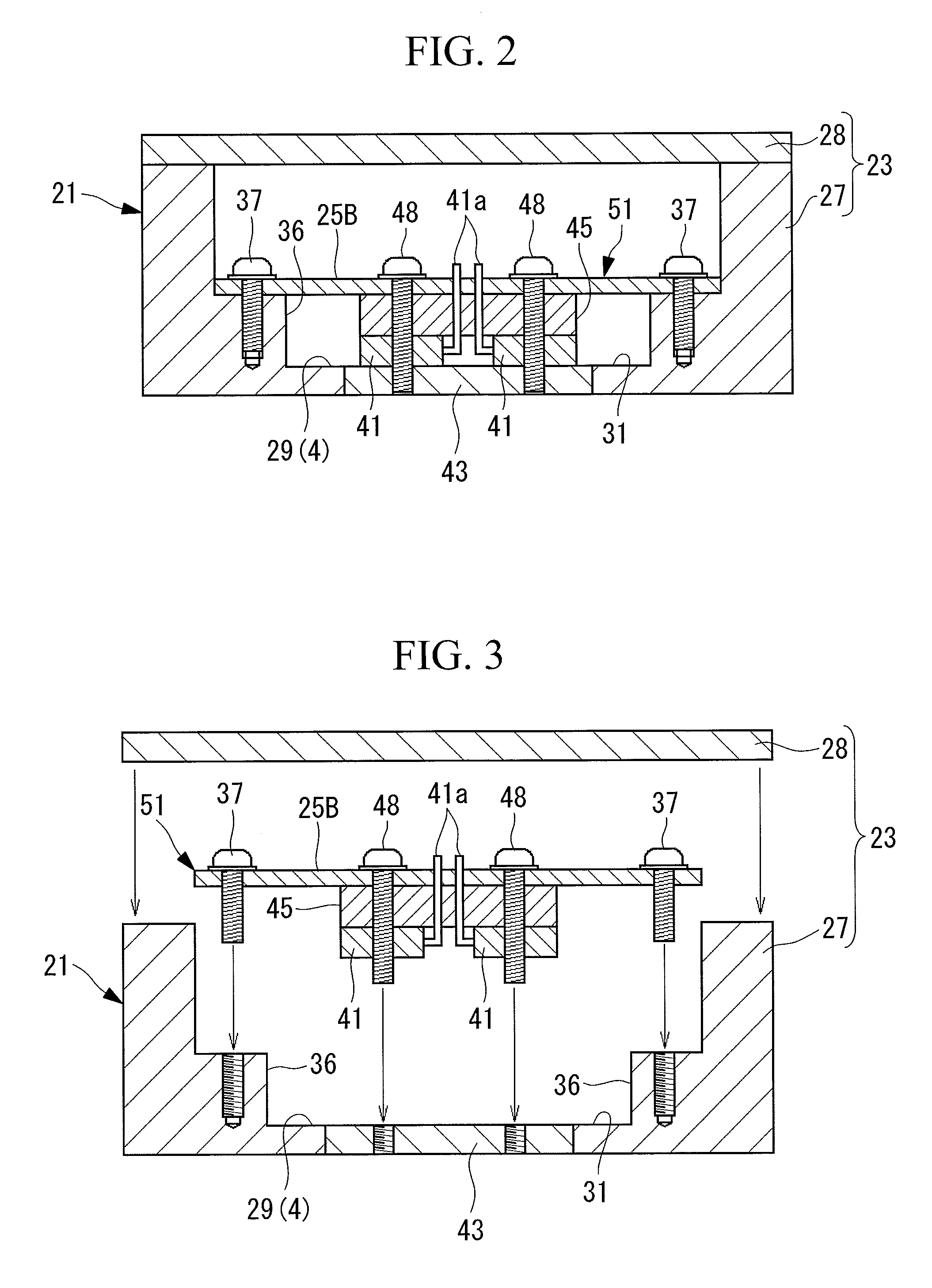
[0039]A first embodiment of the present invention will be described below with reference to FIGS. 1 to 3. FIG. 1 is a vertical sectional view for explaining the schematic configuration of an inverter-integrated electric compressor according to this embodiment. An inverter-integrated electric compressor 1 is a compressor used in a vehicle air conditioner, and the driving rotation speed thereof is controlled by an inverter.
[0040]The inverter-integrated electric compressor 1 has an aluminum-alloy housing 2 serving as an outer shell. The housing 2 is constituted of a compressor housing 3 and a motor housing 4 that are tightly fastened to each other with a bearing housing 5 interposed therebetween by using a bolt 6.
[0041]A commonly known scroll compression mechanism 8 is fitted within the compressor housing 3. A stator 11 and a rotor 12 that constitute a motor 10 are fitted within the motor housing 4. The scroll compression mechanism 8 and the motor 10 are linked with each other via a ma...
second embodiment
[0060]Next, a second embodiment of the present invention will be described with reference to FIG. 4 and FIGS. 5A to 5C.
[0061]In FIG. 4 and FIGS. 5A to 5C, components that are the same as those in the first embodiment shown in FIGS. 1 to 3 are given the same reference numerals, and descriptions thereof will be omitted.
[0062]In the second embodiment, bonding layers 62 are formed on both upper and lower surfaces of a spacer member 61. The bonding layers 62 function as bonding members for bonding the spacer member 61 to the lower board 25B and the IGBTs 41, and can conceivably be composed of an adhesive material, such as an adhesive or double-sided tape, or a heat-weldable joining material, such as solder layers or adhesive resin layers. Although only one bonding layer 62 may be provided on one of the upper and lower surfaces of the spacer member 61, it is preferable that both the upper and lower surfaces be provided with bonding layers 62.
[0063]Unlike the first embodiment, the IGBTs 41...
third embodiment
[0069]Next, a third embodiment of the present invention will be described with reference to FIG. 6.
[0070]In FIG. 6, components that are the same as those in the second embodiment shown in FIG. 4 are given the same reference numerals, and descriptions thereof will be omitted.
[0071]In the third embodiment, the IGBTs 41 are fastened to the heat conducting member 43 using screws 71. Furthermore, recesses 73 for accommodating the heads of the screws 71 are formed in the lower surface of a spacer member 72. Bonding layers 62 similar to those in the second embodiment are used for bonding and positioning between the IGBTs 41 and the spacer member 72 and between the spacer member 72 and the lower board 25B.
[0072]With this configuration, the IGBTs 41 alone are first fastened to the heat conducting member 43 using the screws 71, thereby ensuring reliable heat dissipation. The recesses 73 in the lower surface of the spacer member 72 may alternatively be through-holes extending through the space...
PUM
| Property | Measurement | Unit |
|---|---|---|
| Elasticity | aaaaa | aaaaa |
Abstract
Description
Claims
Application Information
 - R&D
- Intellectual Property
- Life Sciences
- Materials
- Tech Scout
- Unparalleled Data Quality
- Higher Quality Content
- 60% Fewer Hallucinations
Browse by: Latest US Patents, China's latest patents, Technical Efficacy Thesaurus, Application Domain, Technology Topic, Popular Technical Reports.
© 2025 PatSnap. All rights reserved.Legal|Privacy policy|Modern Slavery Act Transparency Statement|Sitemap|About US| Contact US: help@patsnap.com


