Modular electric power system with a renewable energy power generating apparatus

Active Publication Date: 2011-08-11
SANYO ELECTRIC CO LTD
View PDF3 Cites 11 Cited by
  • Summary
  • Abstract
  • Description
  • Claims
  • Application Information

AI Technical Summary

Benefits of technology

[0018]In the ninth electric power system of the present invention, light emitting diodes (LEDs) can be used as the illumination source. Consequently, a low power consumption, extremely long lifetime electric power system can

Problems solved by technology

As a result, this streetlight has drawbacks such as the possibility that the illumination source may not light sufficiently at a given installation site.
For example, solar cells generate relatively little power during the often cloudy winter on the side of Japan facing the Sea of Japan.
Consequently a solar cell charged rechargeable battery powered streetlight installed on the Sea of

Method used


Image

  • Modular electric power system with a renewable energy power generating apparatus
  • Modular electric power system with a renewable energy power generating apparatus
  • Modular electric power system with a renewable energy power generating apparatus

Examples


first embodiment

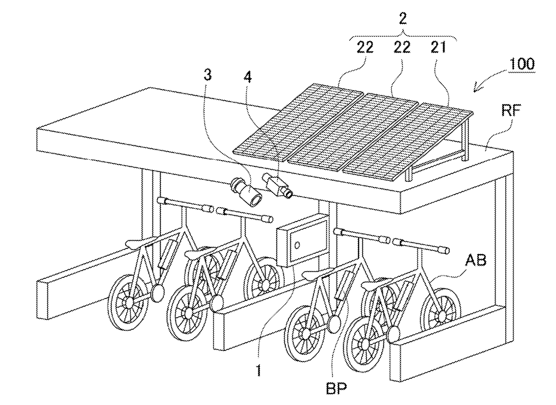
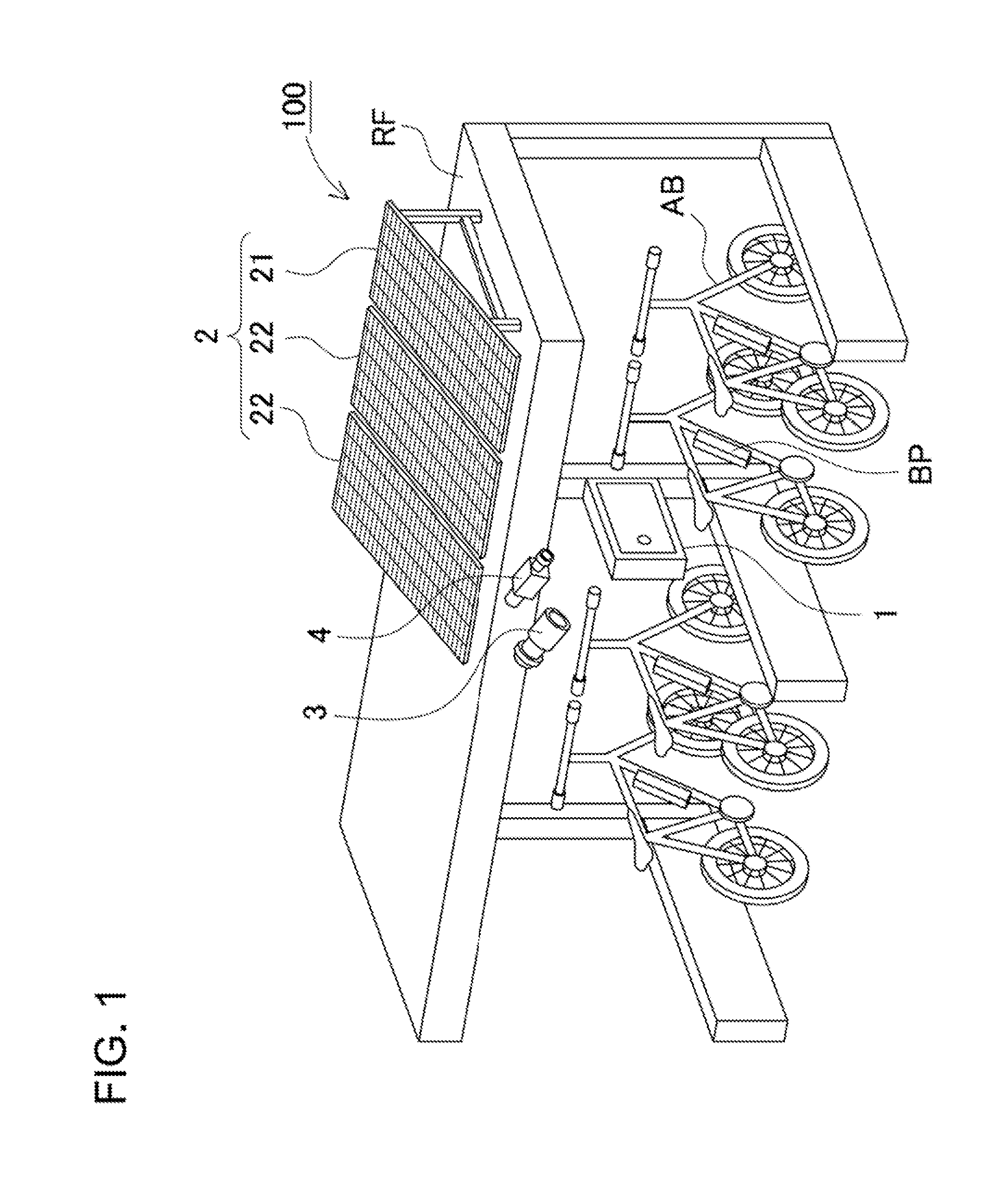
[0027]FIGS. 1-4 show an electric power system 100 for the first embodiment of the present invention. FIG. 1 is a schematic diagram depicting an example of the electric power system 100 applied in a bicycle parking and battery charging structure (for example, for bicycles with electric assist), FIG. 2 is a block diagram showing the interior of the console, FIG. 3 is a block diagram of the electric power system 100, and FIG. 4 is a block diagram of a sub-module 20. These figures show examples of an electric power system 100 that uses solar cell panels as the renewable energy power generating apparatus and a streetlight illumination source 3 as the load.

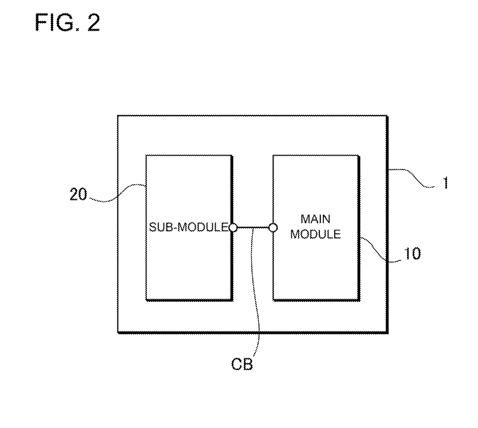
[0028]The electric power system 100 of FIG. 1 is provided with solar cell panels 2 installed on the roof RF of the bicycle parking structure, a module box 1 installed beneath the roof RF at a height that can be reached by the user, and an illumination source 3 used as a streetlight. As shown in the block diagram of FIG. 2, a main module...

second embodiment

[0064]The first embodiment described above uses solar cell panels in a bicycle parking structure that has the added function of battery pack charging. However, the load connected to the electric power system of the present invention is not limited to the load described in that example, and various electrical devices can be connected. For example, an electric power system with a streetlight connected as the load is adopted as the second embodiment described based on FIGS. 5-7. FIG. 5 is an oblique view as viewed from the front of the exterior of the electric power system, FIG. 6 is an oblique view as viewed from the back-side, and FIG. 7 is the oblique view of FIG. 6 with the battery cover removed to expose the battery box. The electric power system 200 shown in these figures is applied as a streetlight power source. Accordingly, the electric power system 200 is attached to the top of a pole 202. As shown in FIGS. 5 and 6, the streetlight is provided with a base 203 attached at an in...


PUM


Abstract

The electric power system is provided with a main module 10 having a switching device 17, and a sub-module 20. The output-side of the sub-module 20 sub-reverse current protection diode 24 is connected to a connection point CP between the main module 10 main reverse current protection diode 14 and the switching device 17 to allow power to be supplied to the load from the sub-battery pack 21 through the sub-reverse current protection diode 24 and the switching device 17. The main module 10 main control circuit 13 controls the switching device 17 ON and OFF to supply power from both the main module 10 main battery pack 11 and the sub-module 20 sub-battery pack 21 to light an illumination source 3.

Description

BACKGROUND OF THE INVENTION[0001]1. Field of the Invention[0002]The present invention relates to an electric power system that stores power generated from renewable energy in rechargeable batteries, and at night powers a source of illumination with the rechargeable batteries.[0003]2. Description of the Related Art[0004]A streetlight has been developed that charges rechargeable batteries via renewable energy and lights an illumination source with the charged batteries at night.[0005]Refer to Japanese Laid-Open Patent Publication 2007-26962.SUMMARY OF THE INVENTION[0006]JP 2007-26962 A cites a streetlight with rechargeable batteries that are charged by photovoltaic device (solar cell) output during the day to light an illumination source with the charged rechargeable batteries at night.[0007]Since the streetlight generates electricity with solar cells to light an illumination source at night, it has the characteristic that it can light the illumination source at night by using renewab...

Claims


Application Information

Patent Timeline
IPC IPC(8): F21L4/08H01M10/46
CPCH02J1/10H02J9/00H02J7/34H02J7/0027H02J7/0014H02J2310/48
Inventor YAMAGUCHI, MASAO
Owner SANYO ELECTRIC CO LTD
Why Eureka
Try Eureka