Switching power supply device using switching regulator

Inactive Publication Date: 2011-08-11
CANON KK
View PDF20 Cites 15 Cited by
  • Summary
  • Abstract
  • Description
  • Claims
  • Application Information

AI Technical Summary

Benefits of technology

[0006]Hence, the present invention solves at least one of such problems and other problems. For example, the present invention provides an overload protection circuit which can maintain the reliability of elements such a

Problems solved by technology

However, depending on the arrangement of the overload protection circuit, the characteristics (drooping characteristics) of an output voltage with respect to an output current of the switching regulator unwantedly change to [\(backslash)] type characteristics.
In a switching power supply device having suc

Method used


Image

  • Switching power supply device using switching regulator
  • Switching power supply device using switching regulator
  • Switching power supply device using switching regulator

Examples


Example

First Embodiment

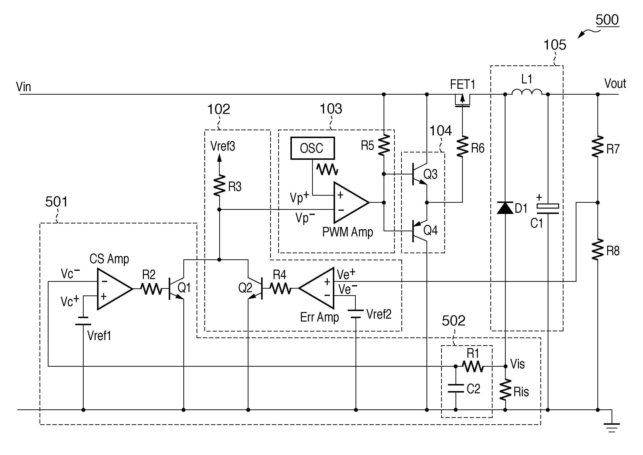
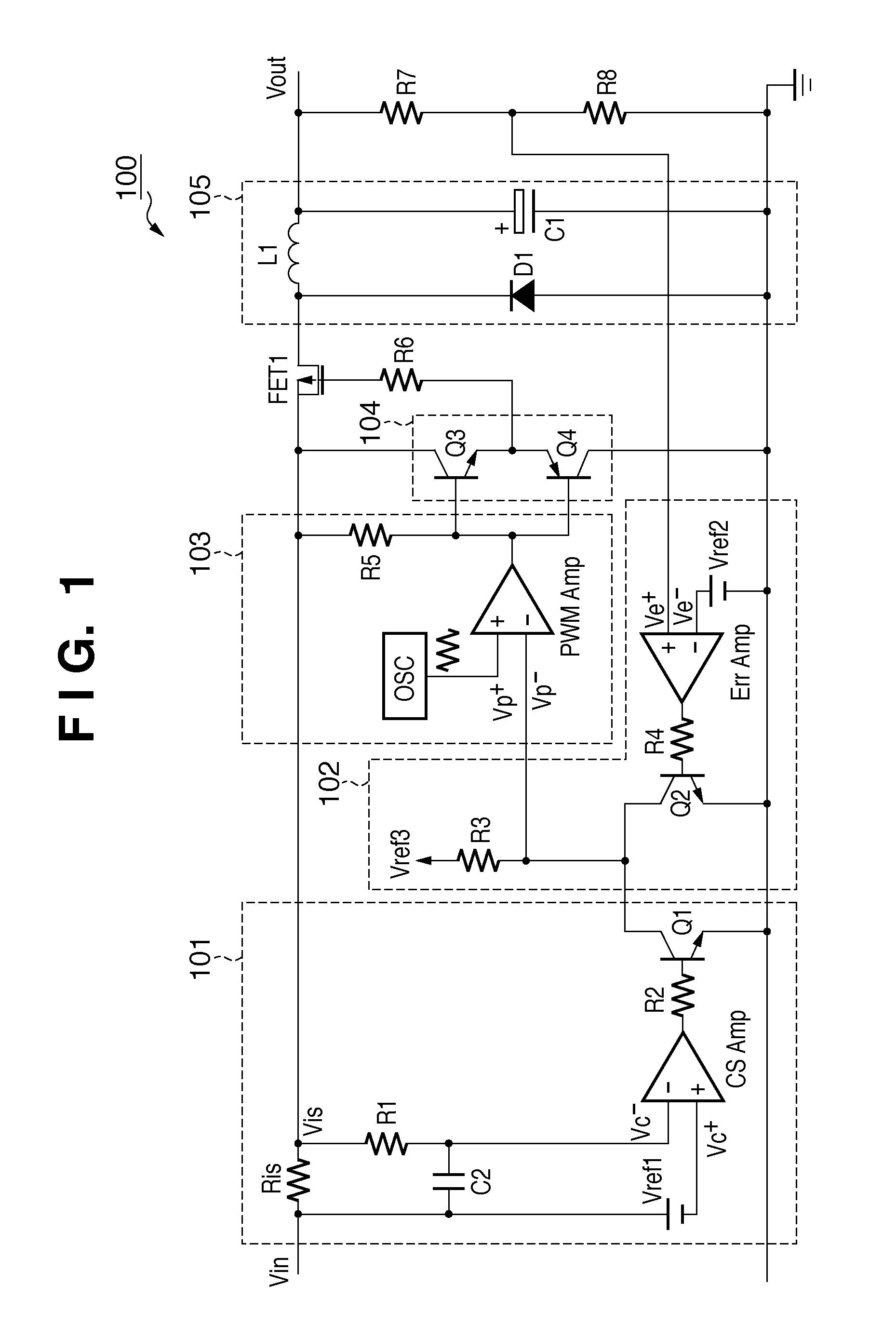
[0043]FIG. 5 is a circuit diagram showing a DC / DC converter according to the first embodiment of the present invention. This embodiment will explain a DC / DC converter 500 as an example of a switching power supply device. A characteristic feature of the first embodiment lies in that overload protection is performed by detecting a current flowing through a diode D1 as a rectifying element for a circulate current in the DC / DC converter 500 by an overload protection circuit 501. As for items which are common to those described using FIGS. 1 to 4B, the following description will be simplified by denoting them by the same reference numerals.

[0044]Referring to FIG. 5, to a first terminal of an FET1 as a switching element, a first terminal of an inductor L1 and that of a diode D1 as a first rectifying element are connected. To a second terminal of the inductor L1, a first output terminal used to connect a load, and a first terminal of a capacitor C1 are connected. To a secon...

Example

Second Embodiment

[0057]FIG. 9 is a circuit diagram showing a switching power supply device of the second embodiment. A DC / DC converter 900 is a forward isolation type DC / DC converter. The DC / DC converter 900 is characterized in that overload protection is performed by detecting a current flowing through a diode D1 for a circulate current. Note that the following description will be simplified by denoting parts common to the first embodiment by the same reference numerals.

[0058]Referring to FIG. 9, an FET21 as a switching element is connected to a primary coil of a transformer T21. To a secondary coil of the transformer T21, the other terminal of a diode D21 serving as a second rectifying element is connected. One terminal of the diode D21 is connected to an inductor L1. The DC / DC converter 900 is an isolation type DC / DC converter which circulates a current flowing through the inductor L1 when the switching element is disabled by the diode D1.

[0059]An AC voltage of a commercial power...

Example

Third Embodiment

[0066]The third embodiment will explain a power supply system configured by arranging the DC / DC converter 500 described in the first embodiment after the isolation type DC / DC converter 900. FIGS. 12 and 13 are block diagrams showing a power supply device and a device serving as a load according to the third embodiment. An AC / DC converter 1201 is a first converter which transforms and outputs an input voltage. The DC / DC converter 500 is a second converter which further transforms the output voltage of the AC / DC converter 1201 to obtain a second output voltage. A control unit 1202 serves as a switching circuit which switches the output voltage of the first converter to one of a high voltage and low voltage in accordance with a state of an electronic device to which the second output voltage is supplied.

[0067]The AC / DC converter 1201 includes the isolation type DC / DC converter 900, and transforms an AC voltage of a commercial power supply AC into a DC voltage Vout2. The...


PUM


Abstract

A power supply device includes, for example, a switching element, a rectifying circuit having a first rectifying element, and a control circuit which controls an output of the rectifying circuit. In particular, the power supply device includes a detection unit which detects a current flowing through the first rectifying element, and an output reduction unit which reduces the output of the rectifying circuit as an output of the switching power supply device. The output reduction unit changes a switching state of the switching element when the detection result of the detection unit exceeds a predetermined value.

Description

BACKGROUND OF THE INVENTION[0001]1. Field of the Invention[0002]The present invention relates to a switching power supply device including a switching regulator such as a DC / DC converter.[0003]2. Description of the Related Art[0004]A switching power supply device including a switching regulator such as a DC / DC converter has prevailed as a power supply device for, for example, an image forming apparatus. In such a power supply device, a large-capacity capacitor is required to attain slow voltage and current changes with respect to load variations. Japanese Patent Laid-Open No. 2000-023355 has proposed means for suppressing output voltage variations based on a notice signal that gives notice of an abrupt change in the impedance of a load.[0005]A switching regulator generally includes an overload protection circuit. However, depending on the arrangement of the overload protection circuit, the characteristics (drooping characteristics) of an output voltage with respect to an output curr...

Claims


Application Information

Patent Timeline
IPC IPC(8): G03G15/00H02M3/335
CPCG03G15/5004H02M3/156H02M1/32G03G15/80
Inventor MATSUMOTO, SHINICHIRO
Owner CANON KK
Why Eureka
Try Eureka