Method for forming polarization reversal

a technology of spontaneous polarization and polarization, applied in the field of method for forming a can solve the problems of difficult to form a desired ridge structure, difficult to form a homogeneous ferroelectric spontaneous polarization reversal, and substrate is easy to break, so as to achieve the effect of effectively applying an electric field to the substra

Active Publication Date: 2011-08-18
SUMITOMO OSAKA CEMENT CO LTD +1
View PDF4 Cites 2 Cited by
  • Summary
  • Abstract
  • Description
  • Claims
  • Application Information

AI Technical Summary

Benefits of technology

[0076]This makes it possible to generate nucleuses within the region where it is desired to form a ferroelectric spontaneous polarization reversal as well as its periphery and to improve nuclear growth density. It is possible to achieve a homogeneous ferroelectric spontaneous polarization reversal even when a large dimension of a ferroelectric spontaneous polarization reversal region is formed.
[0094]In accordance with the sixteenth aspect of the invention, it is possible to apply an electric field into the substrate effectively even when the concave portion is formed on the top face or bottom face of the substrate because the electric field is applied via the liquid electrode.

Problems solved by technology

Also, it becomes difficult to form a ferroelectric spontaneous polarization reversal homogeneously because of in-plane variation of wafer thickness and differences in voltage effects that are caused by dispersion of electric resistance of electrodes that apply an electric field.
However, it is difficult to form a desired ridge structure in the chemical removal process because the etching velocity and / or etching direction priority between the ferroelectric spontaneous polarization reversal region and the other region is different, and also, there is a disadvantage that in a mechanical removal process the substrate gets easy to break because the substrate receives much of a shock entirely.
However, the ferroelectric spontaneous polarization reversal method in FIG. 9 has some negative effects such as the substrate becomes easy to break because the electric filed becomes concentrated at the edges 137 of electrode 133 formed on the ridge structure in FIG. 9(d), and further, when forming a ferroelectric spontaneous polarization reversal over the ridge structure and other regions, voltage adjustment in a ferroelectric spontaneous polarization reversal becomes complicated because the ridge and other regions are different in thickness and therefore, are different in strength of the electric field.
However, the method, for forming a ferroelectric spontaneous polarization reversal using the insulating mask as shown in FIGS. 10 and 11 has a problem that the material for the insulating mask is limited because it is necessary to select the material having electric resistance higher than that of the ferroelectric substrate 101.
Furthermore, although when a resist mask that is widely used as the insulating mask is used here, hard baking treatment is effective in increasing the electric resistance value of a resist mask, it becomes difficult to remove the resist mask after forming a ferroelectric spontaneous polarization reversal.
Moreover, the control accuracy of a ferroelectric spontaneous polarization reversal region declines because unintended micro ferroelectric spontaneous polarization reversal regions (micro-domain) are introduced into the substrate entirely due to the heat treatment, and operation troubles or a degradation of characteristics of a device using a ferroelectric spontaneous polarization reversal structure, such as a wavelength conversion element or an optical modulator, could be caused.
It becomes difficult to control the formation of the ferroelectric spontaneous polarization reversal region accurately.
Further, the method for forming a ferroelectric spontaneous polarization reversal by the electrode pattern as shown in FIG. 1 or the insulating mask pattern as shown in FIG. 2 has problems that the fineness and the closeness of a ferroelectric spontaneous polarization reversal region are limited depending on the formation accuracy of a stroke width and / or a spacing of each pattern, and that the production process including to form a ferroelectric spontaneous polarization reversal becomes complicated because extra processes for forming patterns and removing the patterns have to be needed in the production process.

Method used


Image

  • Method for forming polarization reversal
  • Method for forming polarization reversal
  • Method for forming polarization reversal

Examples


Embodiment Construction

[0128]In the following, the preferred embodiments of the present invention are explained in detail.

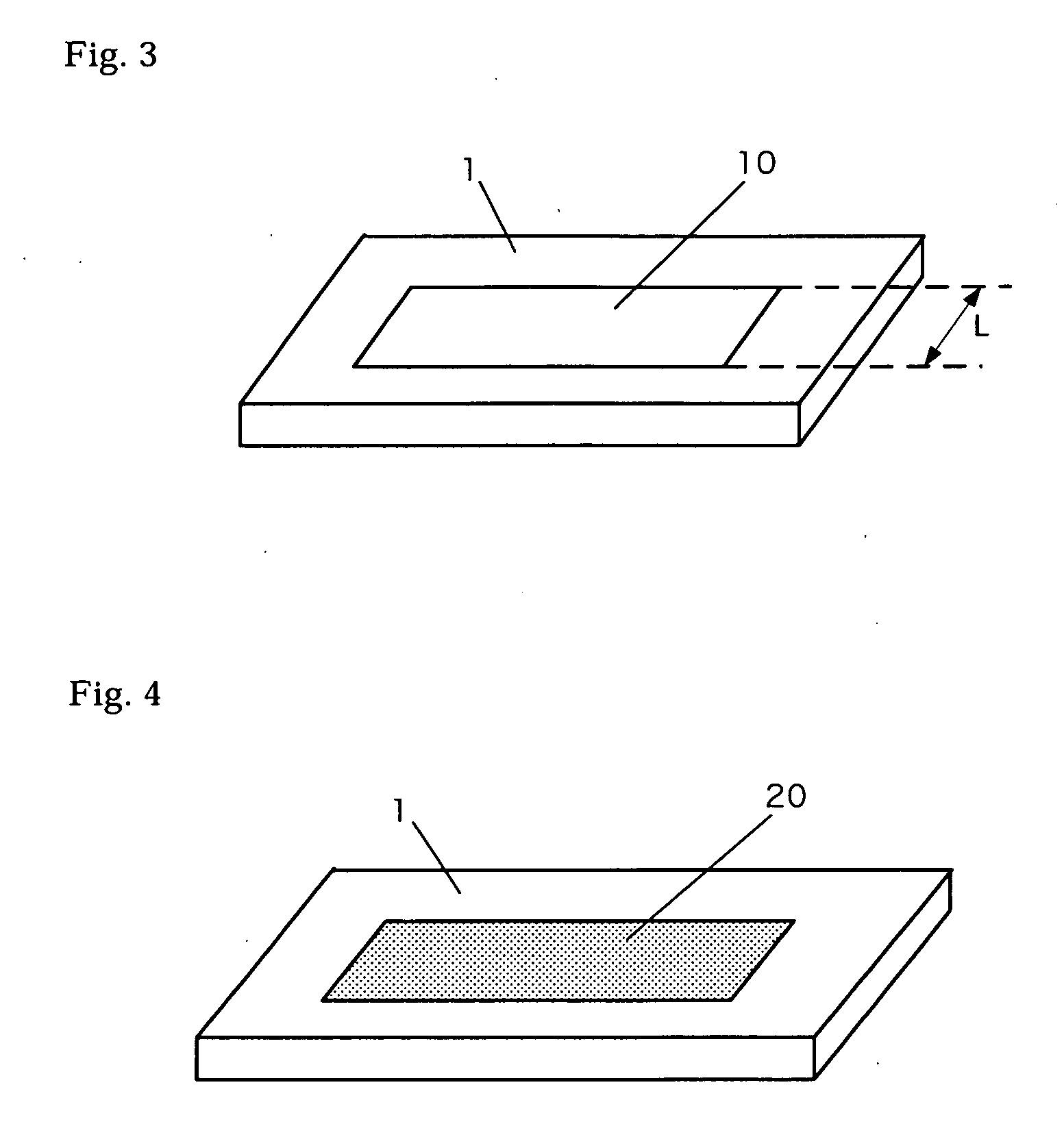
[0129]FIG. 4 is a diagram showing many nucleuses generated on the surface of a ferroelectric substrate 1 for a ferroelectric spontaneous polarization reversal region 20.

[0130]If such nucleuses exist, a ferroelectric spontaneous polarization reversal is expanded around these nucleuses when an electric field is applied into the ferroelectric substrate. Thus, if these nucleuses exist moderately in a desired ferroelectric spontaneous polarization reversal region, it becomes possible to realize homogeneous ferroelectric spontaneous polarization reversal state across a large diameter ferroelectric wafer, even when a ferroelectric spontaneous polarization reversal is simultaneously performed for several large regions of over 25 μm in a ferroelectric spontaneous polarization reversal region width within a large diameter ferroelectric wafer of over 2 inches in diameter.

[0131]A method of applyin...


PUM

PropertyMeasurementUnit
widthaaaaaaaaaa
widthaaaaaaaaaa
diameteraaaaaaaaaa

Abstract

A method for forming a ferroelectric spontaneous polarization reversal in a desired region of a ferroelectric substrate includes the steps of forming, for the desired region of the surface of the ferroelectric substrate, an electrode pattern or a mask pattern composed of aggregates of micropatterns, and then applying a given voltage into the desired region. The configuration of the micropatterns can be a stripe-shaped pattern, an ellipse-shaped pattern, a hexagon-shaped pattern, a network pattern, or a double cross shaped pattern. The method can further include the steps of generating many nucleuses by using the electrode pattern or the mask pattern composed of the aggregates of micropatterns, forming another electrode pattern or another mask pattern corresponding to the desired region, and then applying a given voltage into the desired region to generate a ferroelectric spontaneous polarization reversal around the nucleuses.

Description

[0001]This application is a divisional of patent application Ser. No. 11 / 083,735 filed Mar. 18, 2005, claiming priority of Japan Pat. App. No. 2004-079224 filed Mar. 18, 2004; Japan Pat. App. No. 2004-089890 filed Mar. 25, 2004; and Japan Pat. App. No. 2004-104323 filed Mar. 31, 2004, and contents of all of these applications are hereby incorporated by reference.BACKGROUND OF THE INVENTION[0002](1) Field of the Invention[0003]The present invention relates to a method for forming a ferroelectric spontaneous polarization reversal in a desired region of a ferroelectric substrate, and more particularly to a method for forming a ferroelectric spontaneous polarization reversal that forms on a substrate having an electrooptic effect that is used for an optical element. In addition, it relates to a method for forming a ferroelectric spontaneous polarization reversal, where a ferroelectric substrate has convexo-concave structure on its surface and at a region including one portion of said co...

Claims


Application Information

Patent Timeline
Patent Type & Authority Applications(United States)
IPC IPC(8): H01F7/06
CPCY10T29/4902G02F1/3558
Inventor YAMAMOTO, FUTOSHIICHIKAWA, JUNICHIROOIKAWA, SATOSHIKURIMURA, SUNAOKITAMURA, KENJI
Owner SUMITOMO OSAKA CEMENT CO LTD
Why Eureka
Try Eureka