LED light

a technology of led lights and led light tubes, applied in the field of led lights, can solve the problems of large building space, high etc., and achieve the effects of reducing manufacturing and assembly costs, facilitating signal providing, and being easy to handl

Active Publication Date: 2011-08-18
LUMILEDS
View PDF8 Cites 26 Cited by
  • Summary
  • Abstract
  • Description
  • Claims
  • Application Information

AI Technical Summary

Benefits of technology

Particularly the driving electronics is adapted to transform the signal, which is fed into the driving electronics in the form of a PWM signal, into an analogous signal, particularly a ramp signal, by means of an integrator circuit. In automotive applications it is sometimes easier to provide a signal by means of pulse width modulation (PWM). By means of the integrator a PWM signal with high duty cycle may be trans-formed into a high voltage signal and a PWM signal with low duty cycle into a low voltage signal. Due to the integrator a ramp signal can by applied, which is easier to handle by means the simplified driving electronics.
Preferably the driving electronics comprises at the maximum four connector lines for being connected to a wire leading outside the LED light. The four connector lines may by connected to one current line for connecting a current source to the LED fields, one signal line comprising the signal, one voltage line for providing a constant voltage for the comparators and one collector line for closing the electric circuit. For example only four lines are sufficient for operating a bending light of a motor vehicle. Since a complicated wiring is avoided, the manufacturing and assembling costs are reduced.

Problems solved by technology

It is a disadvantage of these kinds of a LED light, that a large building space is required.
Further a lot of wires are necessary to operate the plurality of LEDs leading to high manufacturing and assembling cost.

Method used


Image

  • LED light
  • LED light
  • LED light

Examples


Embodiment Construction

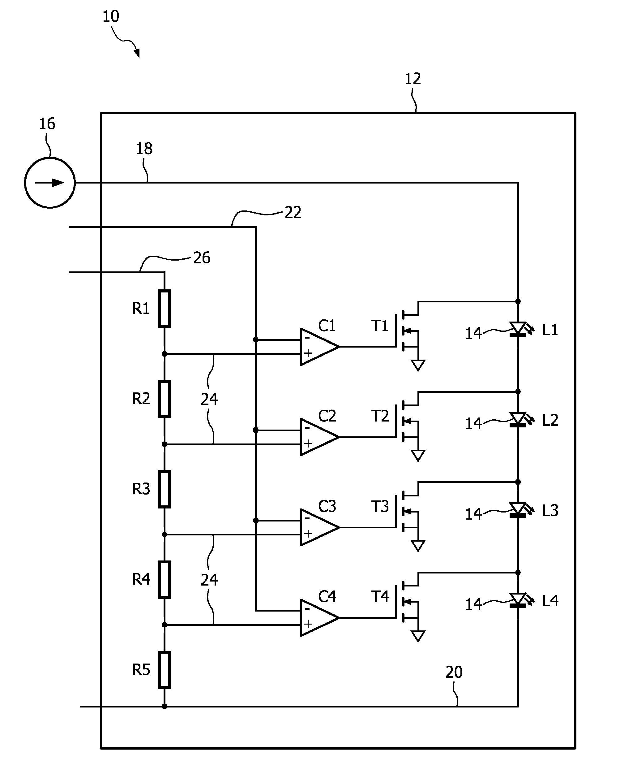
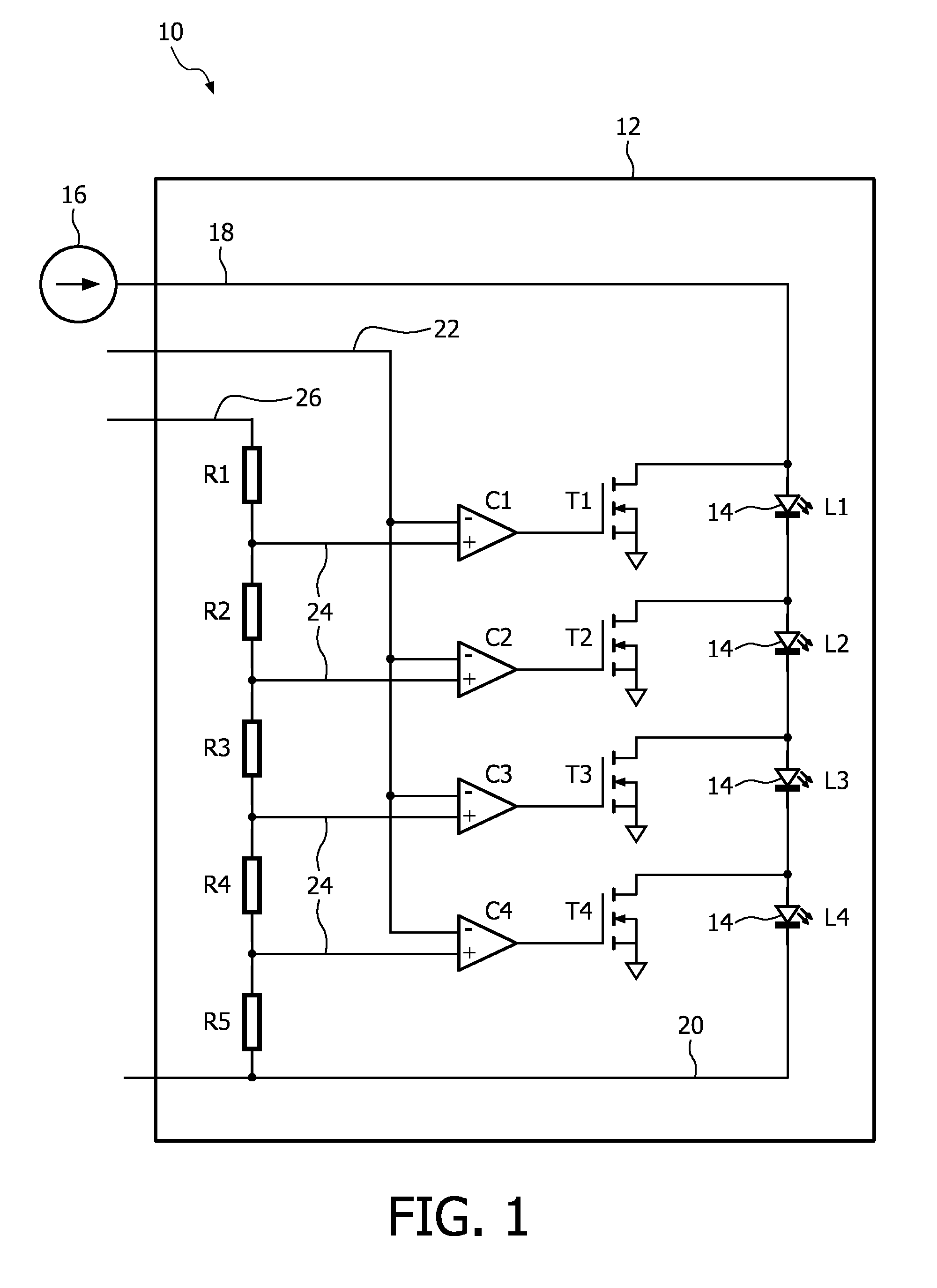
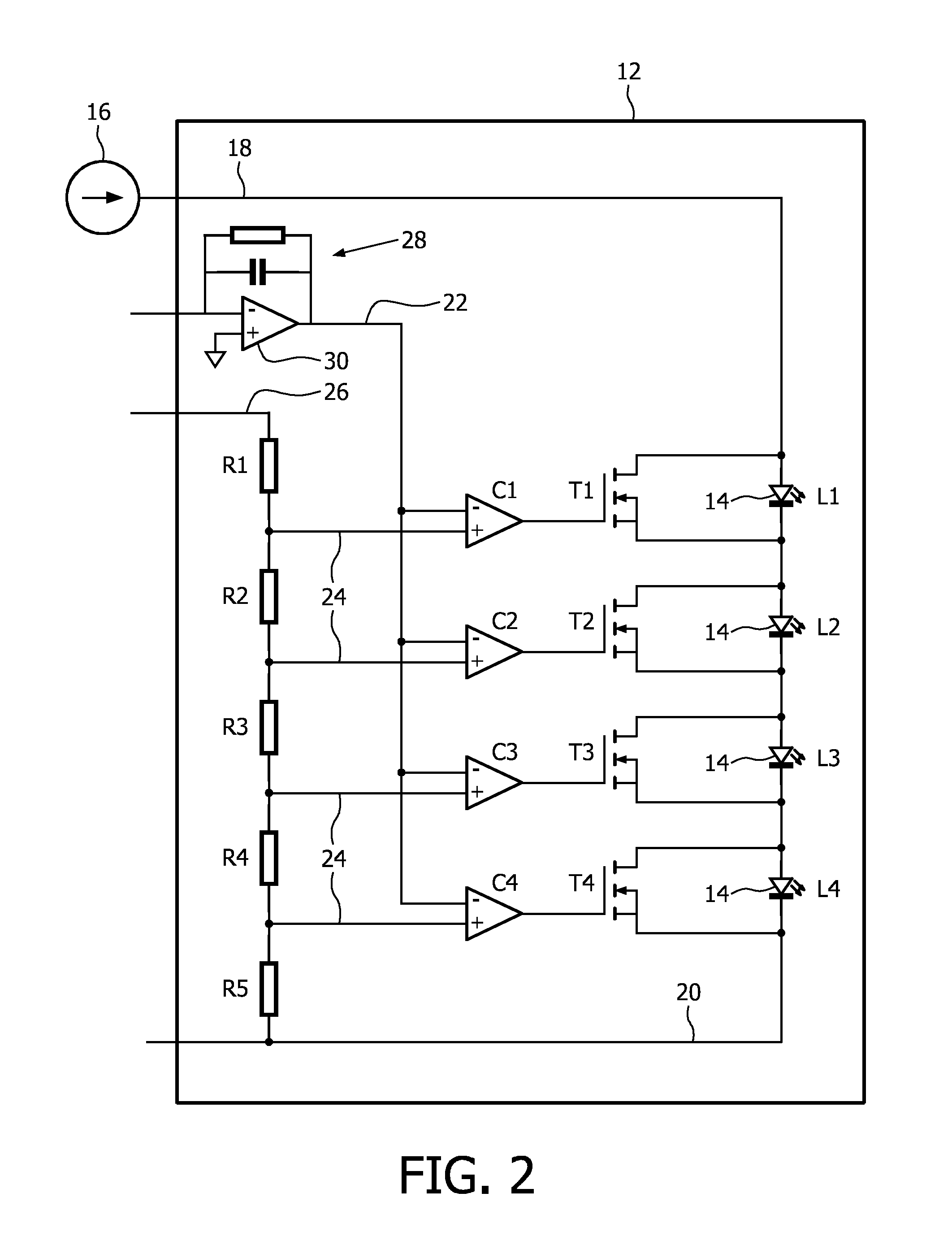
The LED light 10 as illustrated in FIG. 1 comprises a circuit board 12 to which in the illustrated embodiment four LED fields 14 each comprising one light emitting diode (LED) L1, L2, L3, L4 are fastened. The LED light 10 may comprise more or less LED fields 14. The LED fields 14 may comprise two or more LEDs, wherein for sake of clarity only one LED is illustrated. To the LEDs L1, L2, L3, L4 is a current source 16 applied. The current source 16 is located outside the LED light 10 and connected to the LEDs L1, L2, L3, L4 via a current line 18. Since the current source 16 is not part of the LED light 10, the building space of the LED light 10 is comparatively low. For closing the electrical circuit a collector line 20 comprising 0 V is provided. The LED fields 14 are connected in series and are adapted to be switched on or off one by one according to its position in the series.

For operating the LED fields 14 a signal in form of a signal voltage for instance between 0 V and 12 V is ap...


PUM


Abstract

It is provided a LED light (10) for a motor vehicle, comprising several LED fields (14), wherein each LED field (14) comprises at least one LED (L1, L2, L3, L4), a housing (34) for supporting the LED fields (14) and a circuit board (12) comprising a driving electronics for operating the LED fields (14), wherein the LED fields (14) are connected in series by the driving electronics and the driving electronics is adapted to switch on and off each LED field (14) according to its position in the series in dependence of a signal, wherein the circuit board (12) is connectable to an outside of the LED light (10) located current source (16) for applying an electrical current to the LED fields (14), and wherein the circuit board (12) is integrated into the housing (34). Since complicated and/or changing switching orders of the LED fields (14) are not intended the necessary circuit board (12) for providing the corresponding driving electronics may be so small that it may be integrated into the housing (34) of the LED light (10) without significantly increasing the building space. Particularly a lot of wires between a central control unit and the different LED fields (14) are omitted as well as the central control unit itself so that the LED light (10) only requires a small building space.

Description

FIELD OF THE INVENTIONThe invention relates to the field of LED lights, which may be used as lights for a motor vehicle, particularly as bending light.BACKGROUND OF THE INVENTIONFrom DE 10 2004 055 882 A1 a LED light in the form of a bending light for a motor vehicle is known, wherein the bending light comprises several light emitting diodes (LEDs). In dependence of a signal, which can be given by a driving situation, for instance steering angle of a steering wheel, speed of the vehicle or other condition of the car, one or more LEDs are switched on or off one by one for illuminating a curve of a road, when a driver of the motor vehicle wants to take the curve. Each LED is connected by wires to a central control unit, which comprises a driving electronics for operating the LEDs of the bending light, so that each LED is independently from the other LEDs separately turned on or off.From U.S. Pat. No. 6,239,716 B1 a LED light for a motor vehicle is known, wherein a plurality of LEDs is...

Claims


Application Information

Patent Timeline
Patent Type & Authority Applications(United States)
IPC IPC(8): H05B37/02B60Q1/14H05B44/00
CPCB60Q1/12B60Q1/18H05B33/0845B60Q2300/142H05B33/083B60Q2300/122H05B45/48H05B45/10
Inventor HONMA, SHIN'ICHISCHUG, JOSEF A.
Owner LUMILEDS
Why Eureka
Try Eureka