Open-type MRI apparatus, and open-type superconducting MRI apparatus

a superconducting, open-type technology, applied in the field of open-type magnetic resonance imaging, can solve the problems of expensive actual use of piezoelectric elements, and achieve the effect of only generating a small amount of noise and vibration

Active Publication Date: 2011-08-18
FUJIFILM HEALTHCARE CORP
View PDF4 Cites 17 Cited by
  • Summary
  • Abstract
  • Description
  • Claims
  • Application Information

AI Technical Summary

Benefits of technology

[0017]In accordance with the present invention, it is possible to provide an open-type MRI apparatus which generates only a small amount of noise and vibration while maintaining the openness, considering the above-described problems.
[0018]FIG. 1 is a block diagram showing the general configuration of the open-type MRI apparatus to which the present inv...

Problems solved by technology

However, the above-mentioned conventional techniques are complicated in the method of controlling of piezoelectric elements and e...

Method used


Image

  • Open-type MRI apparatus, and open-type superconducting MRI apparatus
  • Open-type MRI apparatus, and open-type superconducting MRI apparatus
  • Open-type MRI apparatus, and open-type superconducting MRI apparatus

Examples


first embodiment

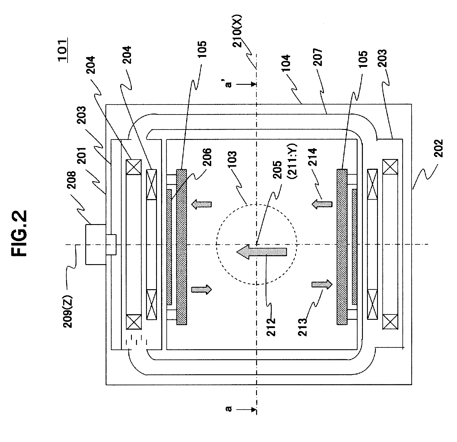
[0074]FIG. 9 shows the first embodiment about disposition and fixation of static magnetic field generating devices (cryostats) and gradient magnetic field coils in an open-type superconducting MRI apparatus. FIG. 9 is an a-a′ cross-sectional view of FIG. 2, and only the outer circumference coil conductor of x-coil 301 is indicated by broken lines regarding gradient magnetic field coil 105.

[0075]In the present embodiment, the origin of the x-y coordinate of gradient magnetic field coil 105 is coincided with origin 205 of an X-Y coordinate of the cryostat, and the x-axis (or y-axis) of gradient magnetic field coil 105 is displaced (offset) for the portion of angle α with respect to the X-axis (or Y-axis) of cryostat 202.

[0076]Gradient magnetic field coils 105 are fixed to cryostat 202 at four places of two places on the x-axis and two places on y-axis by bolts 701, 702, 703 and 704 (displayed by  in the diagram). For the fixation at the four places, the attaching holes are formed in ...

second embodiment

[0084]While the above-described first embodiment is an example for suppressing the vibration having the maximum value on the x-axis and the y-axis of x-coil 301 and y-coil 302, the second embodiment adds the vibration suppression of z-coil 303 to the first embodiment.

[0085]In FIG. 11, gradient magnetic field coil 105 is disposed having offset angle α with respect to cryostat 202. Gradient magnetic field coil 105 is fixed on the imaging space side of cryostat 202 by bolts 701, 702, 703 and 704 on the x-axis and the y-axis. In the present embodiment, the position of the z-axis of gradient magnetic field coil 105 is further fixed to the position of Z-axis 205 of cryostat 202 by bolt 705.

[0086]The fixed position of bolt 705 which is newly added in the present embodiment is the central position of the whorled pattern of z-coil 303, thus poses no problem to a coil pattern.

[0087]By such fixation, the vibration suppressing behavior to be described below is generated.[0088](3) Since the posi...

third embodiment

[0090]The third embodiment adds the vibration suppression having the maximum value in the respective central portions of a pair of whorled coils in x-coil 301 and y-coil 302, to the above-described embodiment 2.

[0091]In FIG. 12, in addition to the above-described second embodiment, the fixed portions 706, 707, 708 and 709 are further provided (701˜705 are not shown in the diagram). Those fixed portions 706, 707, 708 and 709 are provided at the central portion of each pair of whorled coils in x-coil 301 and y-coil 302. By such fixation, the vibration generated in the central regions of the whorled coils described using FIG. 7 can be suppressed.

[0092]Since the above mentioned fixed portions 706˜709 are positioned inside of the whorled pattern in z-coil 303 and the method described in the first and the second embodiments to fix gradient magnetic field coil 105 to the cryostat by clamping with a bolt from the imaging space side cannot be applied, for example, the turnbuckle method or th...


PUM


Abstract

Provided is an open-type MRI apparatus comprising a pair of magnetic field generating means arranged to face each other across a space for imaging an object, static magnetic field generating means holding means for holding the pair of static magnetic field generating means at a predetermined interval, and a pair of tabular gradient magnetic coil structures arranged on the imaging space side of the static magnetic field generating means.
The open-type MRI apparatus is characterized in that the individual tabular gradient magnetic coil structures are fixed on their individually facing static magnetic field generating means at a plurality of positions for suppressing the deformations, which occur in the gradient magnetic coil structures, by the Lorentz forces which act, when driving electric currents are fed to gradient magnetic coils, on the coil conductors.

Description

TECHNICAL FIELD[0001]The present invention relates to an open-type magnetic resonance imaging (hereinafter referred to as MRI) apparatus, particularly to an open-type MRI apparatus having small magnetic oscillation.BACKGROUND ART[0002]An MRI apparatus comprises a static magnetic field generating device for generating a homogeneous static magnetic field in an imaging space, a gradient magnetic field coil for generating a gradient magnetic field, and a high-frequency coil, so as to obtain images effective for medical diagnosis by applying a high-frequency magnetic field from the high-frequency coil to an examining part of an object to be examined placed in a uniform static magnetic field space, detecting a nuclear magnetic resonance (hereinafter referred to as NMR) signal produced from the examining part and generating an image based on the detected signals. The gradient magnetic field coil applies, in the imaging space, to the gradient magnetic field wherein the magnetic intensity is...

Claims


Application Information

Patent Timeline
IPC IPC(8): G01R33/32G01R33/30G01R33/385G01R33/3873
CPCG01R33/3806A61B5/055G01R33/3873G01R33/3854
Inventor TSUDA, MUNETAKASAKAISARA, KENJI
Owner FUJIFILM HEALTHCARE CORP
Why Eureka
Try Eureka