
Apparatus and method for sensing leakage current of battery

Active Publication Date: 2011-08-18
LG ENERGY SOLUTION LTD
View PDF3 Cites 21 Cited by
  • Summary
  • Abstract
  • Description
  • Claims
  • Application Information

AI Technical Summary

Benefits of technology

[0005]The present invention is designed to solve the problems of the prior art, and therefore it is an object of the present invention to provide apparatus and method for sensing leakage current of a battery, which allows to sense leakage current of a battery in an easy and accurate way by means of a simple leakage current sensing circuit.Technical Solution
[0020]According to the present invention, since leakage current of a battery is sensed using a simple leakage current sensing circuit using a DC power, so it is possible to sense leakage current of a battery in early stage and prevent discharge of the battery. Also, it is possible to prevent malfunction or breakdown of internal devices of a vehicle, caused by leakage current, in advance. In addition, it is possible to prevent injury of a person, caused by leakage current of a battery.

Problems solved by technology

If the insulation of the battery is not kept, there occurs leakage current.
If leakage current occurs, it can be primarily a factor of discharge of the battery and malfunction or breakdown of electronic equipment to which the battery is applied.
In particular, if leakage current occurs in a high voltage battery in for example an electric or hybrid vehicle, the leaked current may fatally shock a person.

Method used


Image

  • Apparatus and method for sensing leakage current of battery
  • Apparatus and method for sensing leakage current of battery
  • Apparatus and method for sensing leakage current of battery

Examples


Embodiment Construction

[0035]Hereinafter, preferred embodiments of the present invention will be described in detail with reference to the accompanying drawings. Prior to the description, it should be understood that the terms used in the specification and the appended claims should not be construed as limited to general and dictionary meanings, but interpreted based on the meanings and concepts corresponding to technical aspects of the present invention on the basis of the principle that the inventor is allowed to define terms appropriately for the best explanation. Therefore, the description proposed herein is just a preferable example for the purpose of illustrations only, not intended to limit the scope of the invention, so it should be understood that other equivalents and modifications could be made thereto without departing from the spirit and scope of the invention.

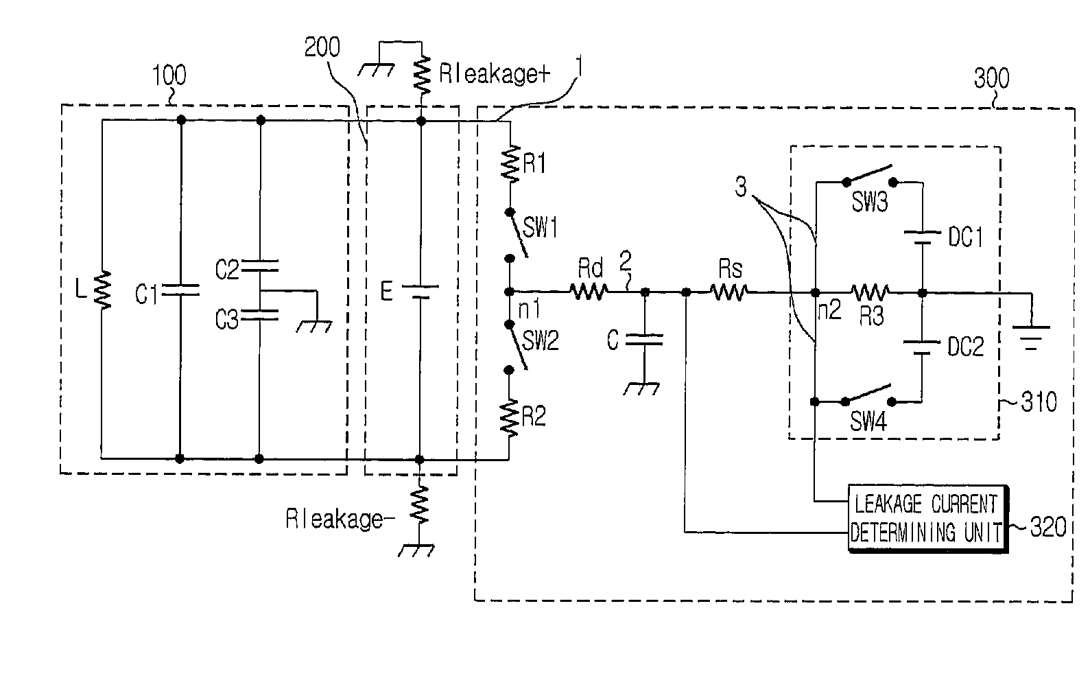
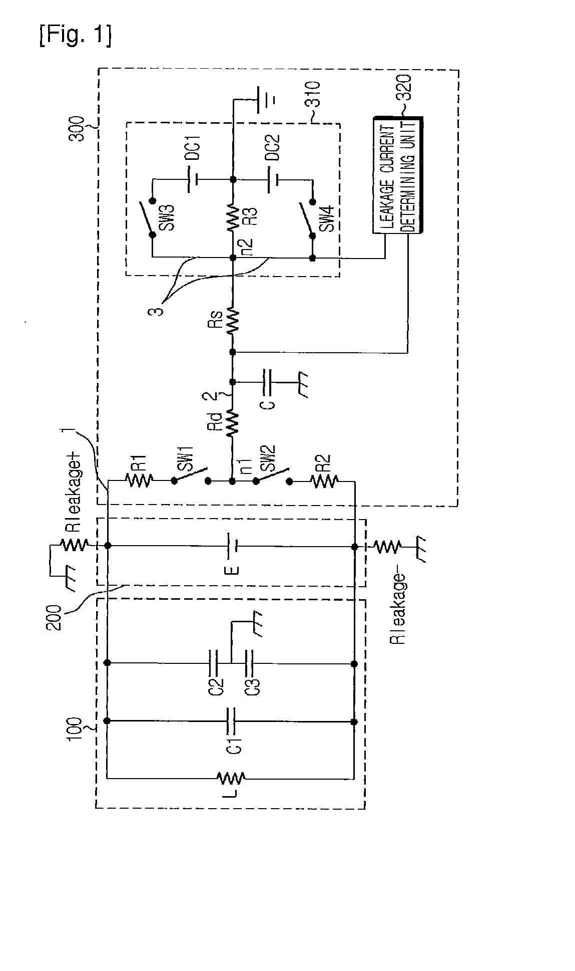
[0036]FIG. 1 is a circuit diagram showing an apparatus for sensing leakage current of a battery according to a preferred embodiment of...


PUM


Abstract

An apparatus for sensing leakage current of a battery includes a voltage distribution node installed on a first conductive line connecting both terminals of a battery; first and second switches installed between the voltage distribution node and positive / negative terminals of the battery; an insulation resistance and a current sensing resistance installed on a second conductive line connecting the voltage distribution node to a ground; a DC voltage applying unit for applying positive / negative DC voltage to a ground-side end of the current sensing resistance to induce potential difference between the voltage distribution node and the DC voltage applying node; and a leakage current determining unit for sensing magnitude of electric current flowing through the current sensing resistance according to the induced potential difference in turning-on state of the switches, and then determining leakage current by checking whether the magnitude of electric current is out of standard level over threshold value.

Description

TECHNICAL FIELD[0001]The present invention relates to apparatus and method for sensing leakage current of a battery, and more particularly to apparatus and method for sensing leakage current of a battery, which may sense leakage current of a battery adopted to a battery power supply system that requires high voltage, such as an electric vehicle or a hybrid vehicle.BACKGROUND ART[0002]In recent, as the interest on electric or hybrid vehicles not using fossil energy but using electric energy due to exhaustion of fossil fuels and environmental pollution is increased, the study on electric or hybrid vehicles is actively progressed. An electric or hybrid vehicle needs electric energy to drive a motor used for the vehicle, and the electric energy should be supplied by means of a battery.[0003]A battery used for the electric or hybrid vehicle generally adopts a secondary battery, which may repeat a discharging process for converting chemical energy into electric energy and a charging proce...

Claims


Application Information

Patent Timeline
IPC IPC(8): G08B21/00G01N27/416G06F19/00
CPCG01R31/3679G01R31/025G01R31/392G01R31/52G01R31/36
Inventor AKIMOV, VOLODYMYRKANG, JU-HYUN
Owner LG ENERGY SOLUTION LTD
Learn More