Spherical Electronic LCD Display

a display and electronic technology, applied in the field of electronic displays, can solve the problems of increasing the problem, requiring a large amount of storage space, and not being able to meet the needs of instruments, and achieve the effect of minimizing cost and adding depth

Inactive Publication Date: 2011-08-18
DZIAMA ROBIN
View PDF54 Cites 24 Cited by
  • Summary
  • Abstract
  • Description
  • Claims
  • Application Information

AI Technical Summary

Benefits of technology

[0012]In some preferred embodiments, at least one layer of the spherical display is transparent, thereby providing an additional dimension of depth by enabling the transparent layer to electronically superimpose displayed information on top of other information displayed below the transparent layer. These embodiments use liquid crystal display (LCD) technology or optical light emitting diode (OLED) technology to electronically generate the images, while remaining transparent in regions where images are not being displayed.
[0013]In some of these embodiments, a traditional, opaque object such as a printed world globe is contained within the transparent spherical display, thereby minimizing cost while allowing the transparent display to superimpose onto the conventional globe selected informatio

Problems solved by technology

This presents a problem for traditional, printed world globes, because it is not possible for a single globe to simultaneously display all of the types of information that might be desirable, for example in a school classroom.
This problem is increased even further if display of non-terrestrial, spherical information is desired, such as global maps of the moon and/or other planets, or a global representation of star constellations.
However, this approach is inconvenient, requires a large amount of storage space, and does not provide for overlap and comparison of different types of information.
Another disadvantage of traditional world globes is that the density of information presented on the globe can be very high, making it difficult to locate desired items of information.
Also, traditional world globes do not provide an ability to display transitory information on a spherical surface, such as current weather pattern

Method used


Image

  • Spherical Electronic LCD Display
  • Spherical Electronic LCD Display
  • Spherical Electronic LCD Display

Examples


Embodiment Construction

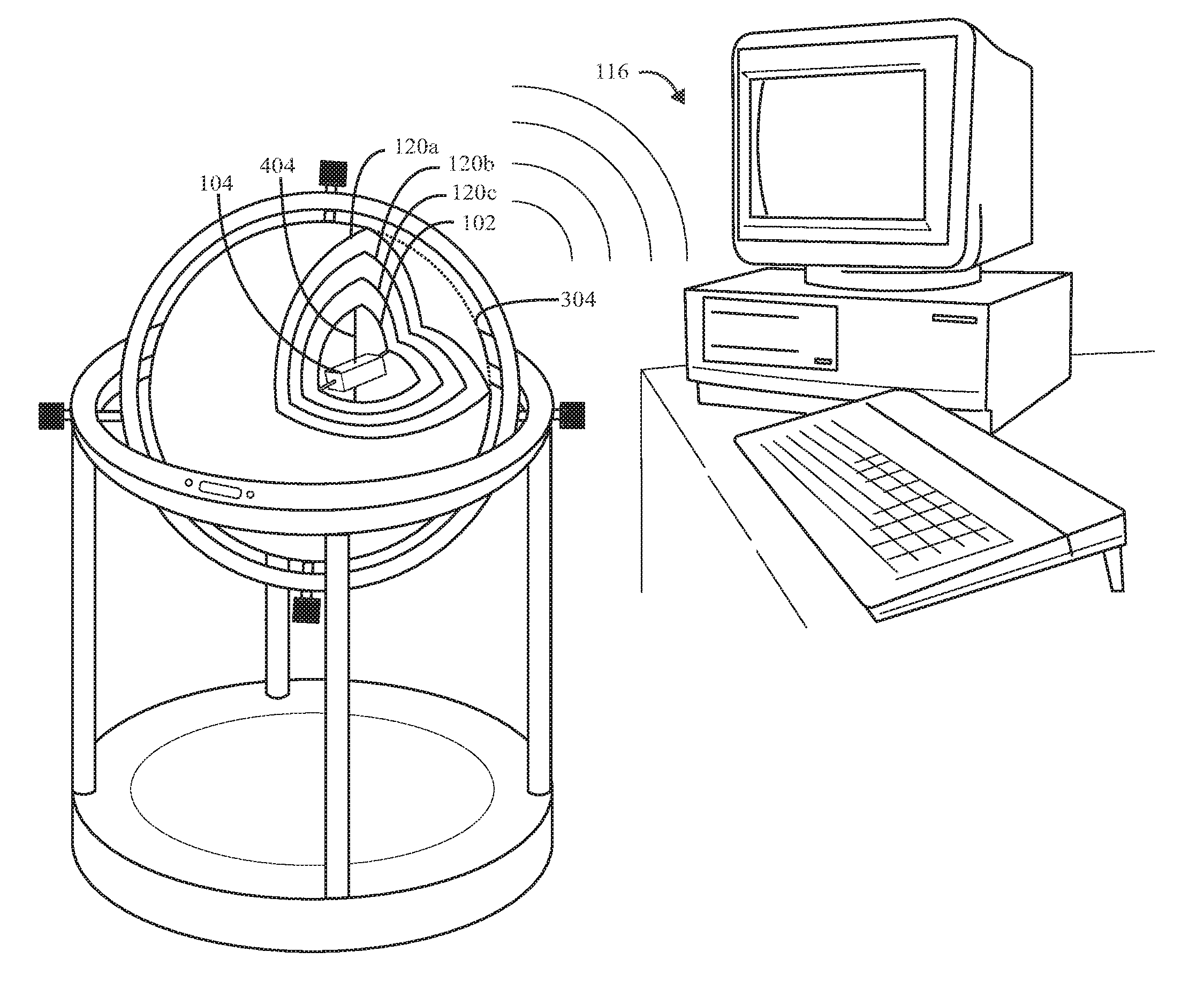
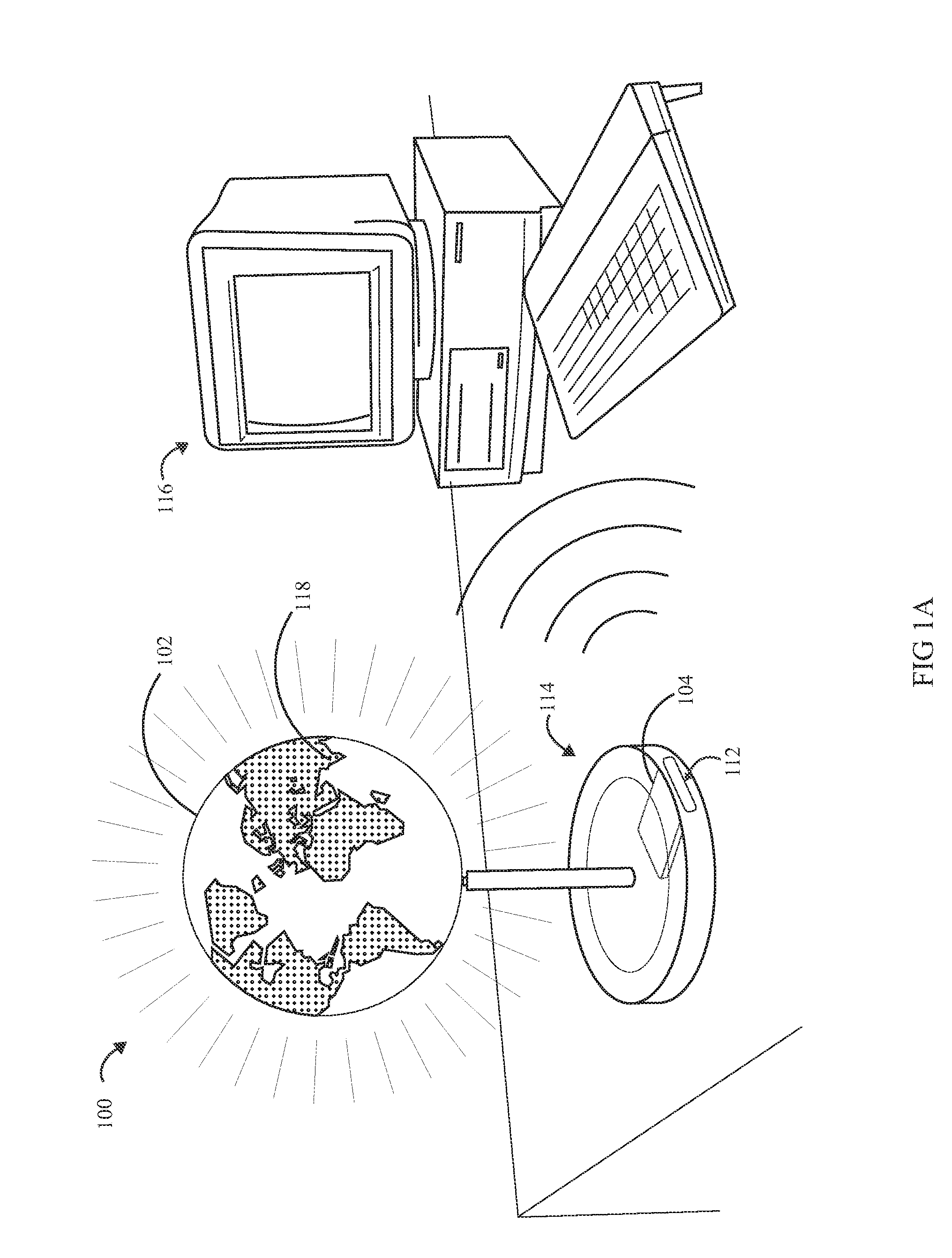
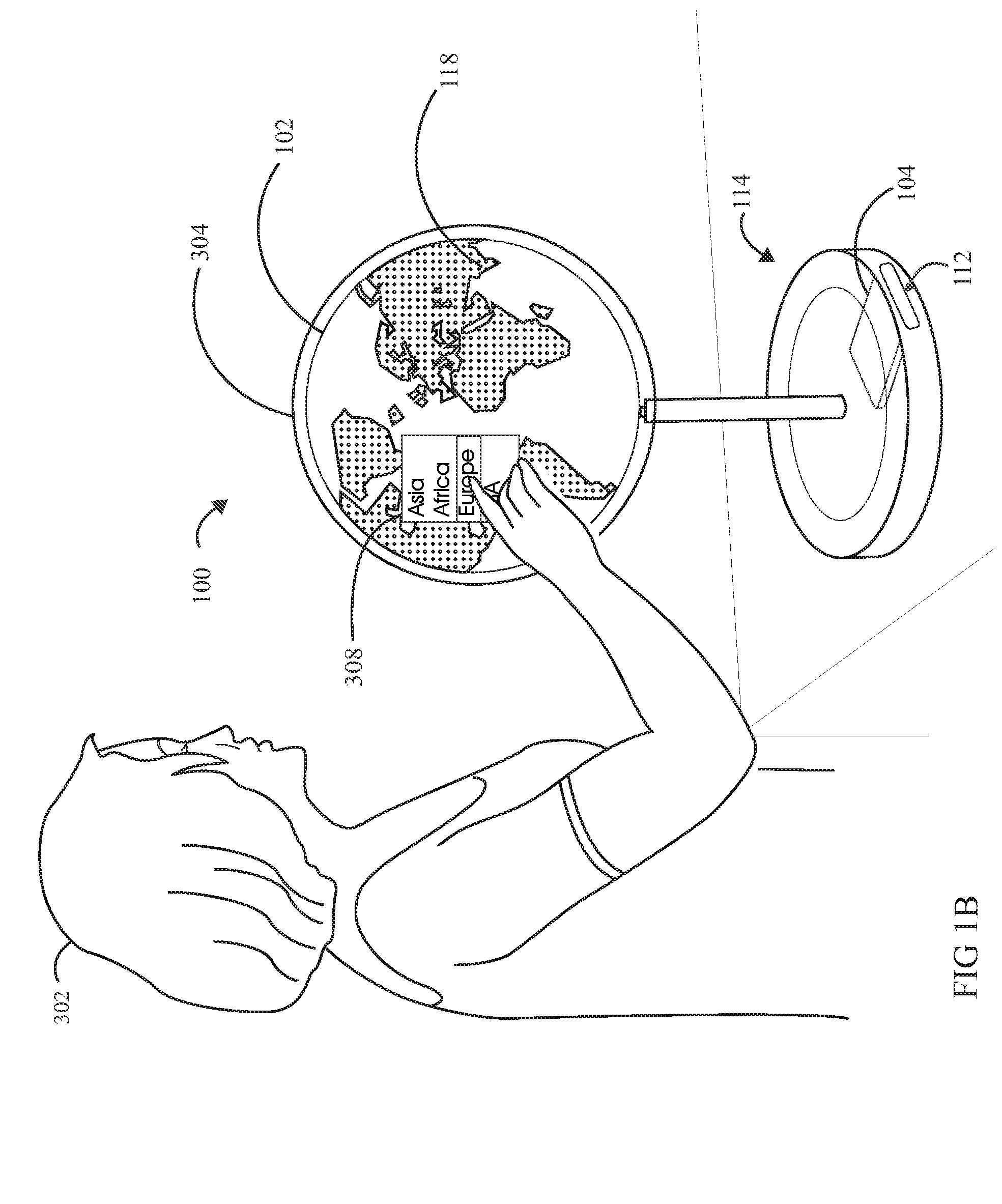
[0025]With reference to FIG. 1A, the invention is an electronically controlled spherical display 100 that is able to display images on a spherical surface 102 by including low energy display technology, such as LCD and / or OLED electronics, within the spherical surface 102. The screen 102 is preferably able to display images in color. Power is supplied to the screen either by an electrical cord and power supply (not shown), or by batteries (not shown) contained either within the spherical display 102 or in a supporting stand 114.

[0026]In the embodiment of FIG. 1A, an electronic control unit 104 is located in a drawer 112 in a support base 114 that supports the spherical display screen 102. The control unit 104 is in wireless communication with a control computer 116. In similar embodiments, the control unit 104 is in wired communication with the control computer 116. In other embodiments, the computer 116 is included within the base unit 114, or within the spherical display screen 10...


PUM


Abstract

A spherical electronic display is disclosed that includes a spherical display screen that is able to display electronically generated images on its surface using electronic display technology included in the surface, and an electronic control unit in communication with the spherical display screen, the electronic control unit being able to cause the spherical display screen to display images. The electronically controlled spherical display uses low energy display technology, such as LCD and/or OLED electronics, included within the spherical surface. This approach avoids the need to project images onto a spherical screen, and thereby avoids any need for high energy optical projectors and their associated costs and maintenance requirements. The spherical display is connectable to an electronic control unit that can be located either within the sphere or within a support base. The electronic control unit can be a conventional computer or a self-contained, dedicated controller.

Description

FIELD OF THE INVENTION[0001]The invention generally relates to electronic displays, and more specifically to spherical electronic displays.BACKGROUND OF THE INVENTION[0002]Most types of information are preferably displayed on a flat surface, including books and most other printed matter, as well as television, movies, and most electronically displayed information such as computer display screens and information displayed on PDA's, MP3 players, cellular telephones, and such like. However, there are certain types of information that are preferably displayed on a spherical surface. The most common example is information pertaining to the earth's surface, which is often displayed on a sphere, or “globe.” Such so-called “world globes,” with maps of the world printed thereon, have long been known. Often, a world globe is mounted on a support that allows movement of the globe about at least one rotational axis, and some globes are mounted on supports that allow rotation about two axes, or ...

Claims


Application Information

Patent Timeline
IPC IPC(8): G09G3/32
CPCG06F3/14G09B27/06G09B27/08G09G2370/16G09G3/3208G09G2300/023G09G2320/0606G09G3/001
Inventor DZIAMA, ROBIN
Owner DZIAMA ROBIN
Why Eureka
Try Eureka