Image-capturing device

a technology of image capture and af lens, which is applied in the direction of optical elements, instruments, television systems, etc., can solve the problem that the decision as to which direction the af lens should be driven to achieve a focus match cannot be made with a high degree of accuracy, and achieve the effect of reducing the offs

Active Publication Date: 2011-08-18
NIKON CORP
View PDF14 Cites 22 Cited by
  • Summary
  • Abstract
  • Description
  • Claims
  • Application Information

AI Technical Summary

Benefits of technology

[0030]According to the 24th aspect of the present invention, in the image-capturing device according to the 23rd aspect, it is preferred that the magnification chromatic aberration correction unit executes the magnification chromatic aberration

Problems solved by technology

However, there is an issue with the autofocusing device in the related art in that since the specific direction in which the AF lens position is offset relative to the focus match po

Method used


Image

  • Image-capturing device
  • Image-capturing device
  • Image-capturing device

Examples


first embodiment

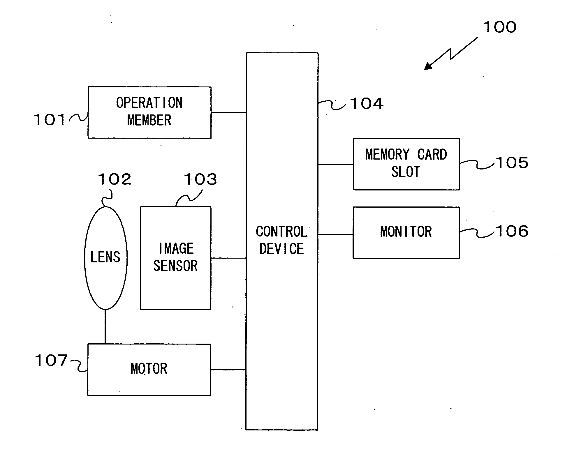
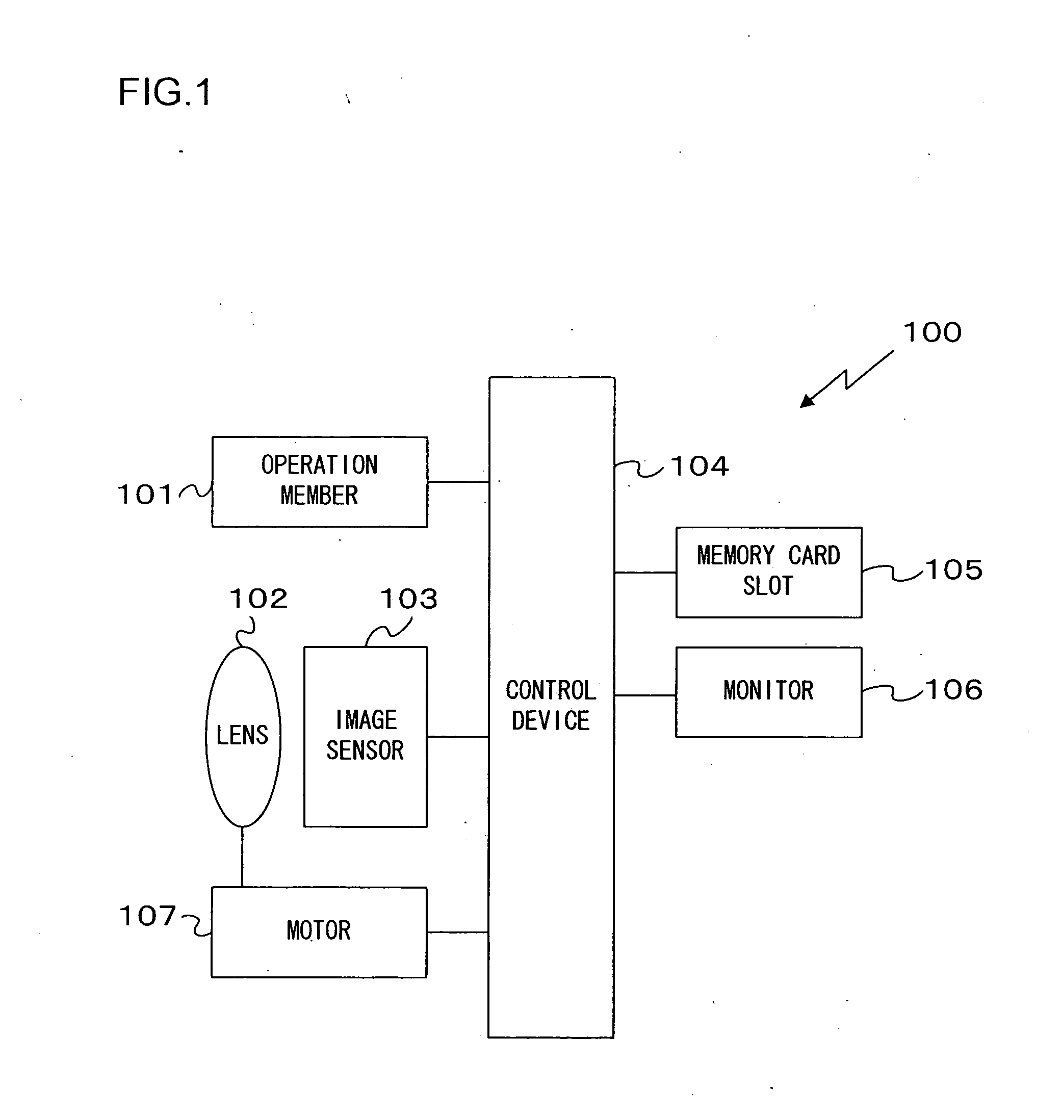
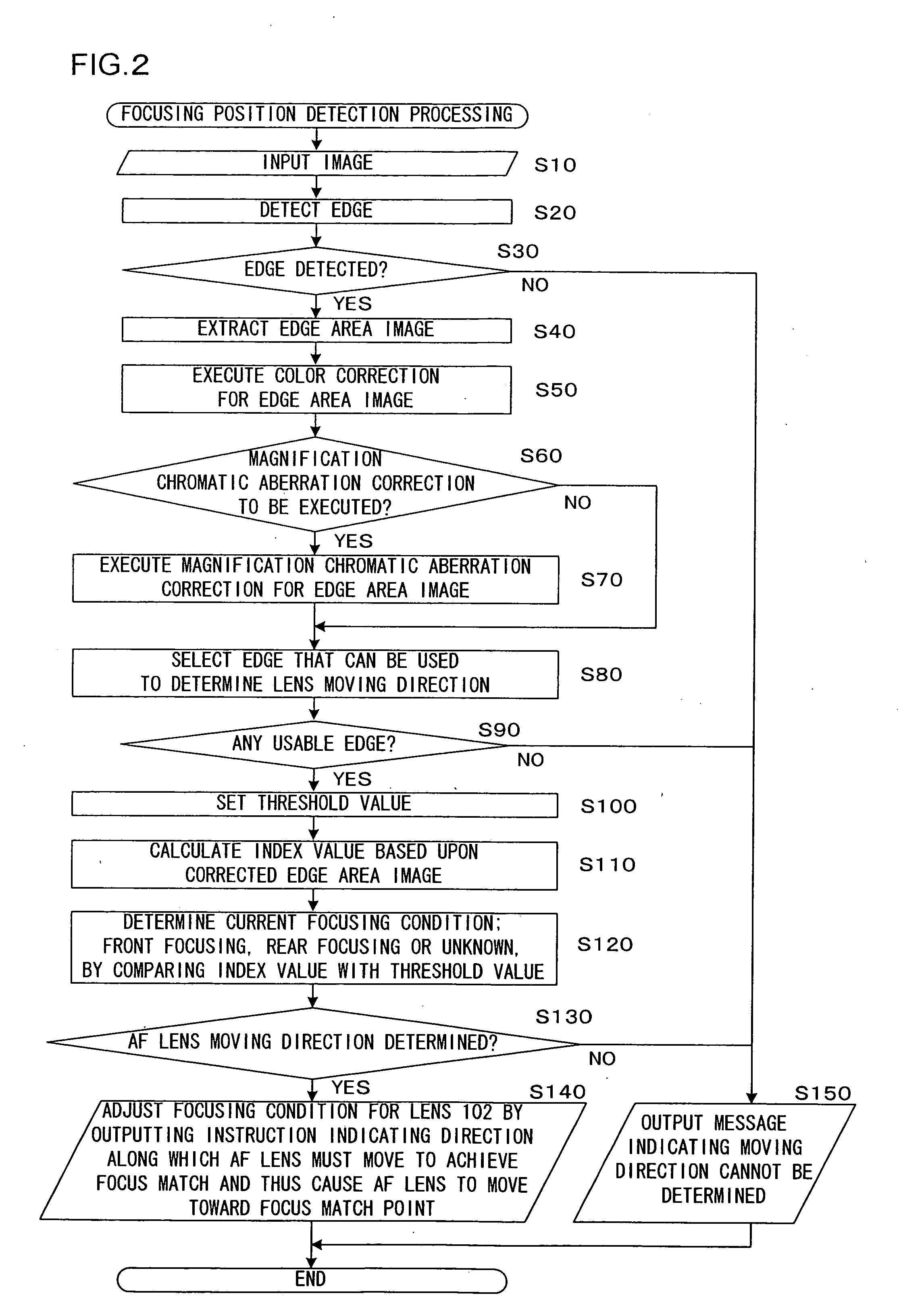
[0068]Assuming that images captured in the camera 100 in the first embodiment are expressed with data in the RGB colorimetric system, different focus match positions are assumed along the optical axis in correspondence to the individual color components in an image input from the image sensor 103 to the control device 104, due to the variance among axial chromatic aberrations occurring in correspondence to the different color components, R, G and B. Accordingly, the decision as to the specific direction along the optical axis the current AF lens position is offset relative to the focus match position is made based upon an edge image in the input image by taking into consideration the varying focus match positions assumed on the optical axis in correspondence to the individual color components due to the variance in the axial chromatic aberration, so as to achieve AF control at all times while the live view image display is on.

[0069]FIG. 2 presents a flowchart of the focusing positio...

second embodiment

[0093]As a live view image input from the image sensor 103 starts, the control device 104 in the camera 100 achieved in the second embodiment executes AF (automatic focus adjustment) processing and thus executes AF control at all times while the live view image is on display by continuously executing focus adjustment while the live view image is on display. In more specific terms, assuming that an image in each frame input from the image sensor 103 to the control device 104 is expressed with data in the RGB colorimetric system, different focus match positions are assumed on the optical axis in correspondence to the individual color components, i.e., the R color component, the G color component and the B color component, due to the variance among the axial chromatic aberrations occurring in correspondence to the individual color components. Accordingly, the current focusing condition is determined based upon a difference between edge blurring widths corresponding to two different col...

third embodiment

[0119]In the second embodiment described above, the conversion edge blurring width difference Δw is calculated for different color component edges corresponding to two color components manifesting axial chromatic aberration and the focusing condition is determined based upon the conversion edge blurring width difference Δw. While axial chromatic aberration causes varying extents of blurring in correspondence to the individual color components, there is an additional factor that may need to be considered, i.e., a change in the levels of resolution corresponding to the individual color components relative to one another, attributable to the processing executed during input image generation, may alter the blurring extents and the blurring width difference between the color components.

[0120]Such a situation may arise, for instance, in an image-capturing device that generates an image by interpolating a raw image read out from a single-chip color image sensor when a raw image read from t...


PUM


Abstract

An image-capturing device includes: an input unit that inputs a subject image formed by an optical system manifesting axial chromatic aberration as an input image; an edge detection unit that detects edges in the input image, each in correspondence to one of color components; a focus adjustment unit that executes focus adjustment for the optical system by detecting contrast differences of the edges corresponding to individual color components having been detected and then moving a focus adjustment lens included in the optical system; and a lens moving direction determining unit that determines a moving direction along which the focus adjustment lens is to move for purposes of focus adjustment based upon the edges corresponding to the individual color components having been detected and the axial chromatic aberration. The focus adjustment unit causes the focus adjustment lens to move along the moving direction determined by the lens moving direction determining unit.

Description

INCORPORATION BY REFERENCE[0001]The disclosures of the following priority applications are herein incorporated by reference: Japanese Patent Application No. 2010-4218 filed Jan. 12, 2010, Japanese Patent Application No. 2010-138440 filed Jun. 17, 2010, Japanese Patent Application No. 2010-274724 filed Dec. 9, 2010 and Japanese Patent Application No. 2010-274725 filed Dec. 9, 2010.BACKGROUND OF THE INVENTION[0002]1. Field of the Invention[0003]The present invention relates to an image-capturing device[0004]2. Description of Related Art[0005]There is an autofocusing device known in the related art that detects a shift in the lens focusing position by using a chromatic aberration manifesting in the light and corrects blurring of light in various colors through focus adjustment executed based upon the detection results (see, for instance, Japanese Laid Open Patent Publication No. H6-138362)SUMMARY OF THE INVENTION[0006]However, there is an issue with the autofocusing device in the relat...

Claims


Application Information

Patent Timeline
IPC IPC(8): H04N9/04
CPCG02B7/365H04N9/045H04N5/23212H04N23/673H04N23/843H04N25/134
Inventor KAWAI, ATSUSHI
Owner NIKON CORP
Why Eureka
Try Eureka