
Apparatus and method for tuning pump speed

a vacuum pump and apparatus technology, applied in the direction of pump control, pump parameter, positive displacement liquid engine, etc., can solve the problems of crude and inaccurate method, inefficiency in energy consumption, and inability to meet the needs of the pump,

Active Publication Date: 2011-08-18
EDWARDS LTD
View PDF18 Cites 25 Cited by
  • Summary
  • Abstract
  • Description
  • Claims
  • Application Information

AI Technical Summary

Benefits of technology

[0022]One advantage of the invention is the conservation of energy realized by the disclosed apparatus and method capable of operating vacuum pumps at optimal speeds. It maintains the simplicity in designing vacuum pumps that might be a little over-specified in order to accommodate various pipe work geometries in different foundries, while enabling vacuum pumps to consume less energy than they otherwise would. The automated pump speed tuning apparatus and method are able to reach the optimal speed faster and in a much more accurate manner than the conventional manual method. This also eliminates room for human errors resulted from manually adjusting the pump speed under stressful conditions.

Problems solved by technology

Although over-specification enables vacuum pumps to accommodate various installation requirements, it has the drawback of inefficiency in energy consumption.
As a result, it tends to consume more energy than what is needed for an acceptable performance.
However, such method is crude and inaccurate.
It may not be able to provide the accuracy level needed for a vacuum pump to operate at an optimal speed.
Furthermore, manual adjustment is inconsistent and prone to errors.
This may cause undesired process variations.

Method used


Image

  • Apparatus and method for tuning pump speed
  • Apparatus and method for tuning pump speed
  • Apparatus and method for tuning pump speed

Examples


Embodiment Construction

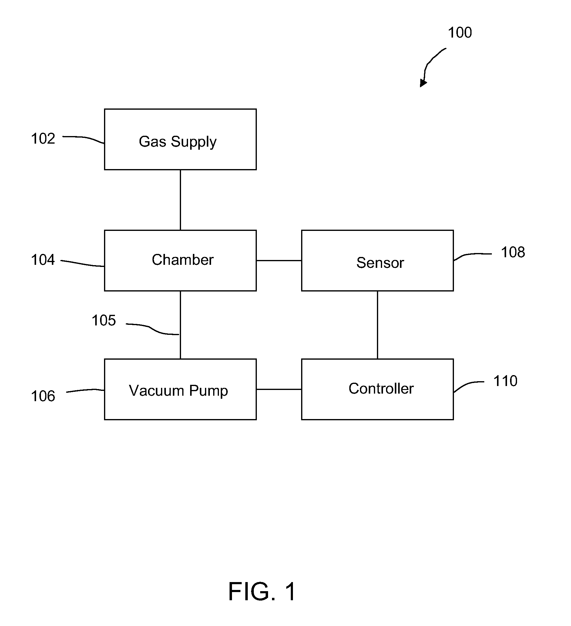
[0011]FIG. 1 illustrates a block diagram of an exemplary apparatus 100 for tuning pump speed in accordance with some embodiments of the invention. The apparatus 100 includes, without limitation, a gas supply 102, chamber 104, vacuum pump 106, sensor 108, and controller 110. The chamber 104 can be a process chamber that receives chemical reactants and other gases from the gas supply 102. The chemical reactants are usually supplied to the chamber 104 in a gaseous state, and can be evacuated from the chamber 104 by the vacuum pump 106 via a fore line 105 connecting in between. The vacuum pump 106 creates a low pressure or partially vacuum environment in the chamber 104.

[0012]In some embodiments of the invention, the chamber 104 is a process chamber in which the chemical reactants can form a thin layer of coating on a semiconductor wafer. In some other embodiments of the invention, the chamber 104 can be a load lock chamber with or without a gas supply attached to it. A load lock chambe...


PUM


Abstract

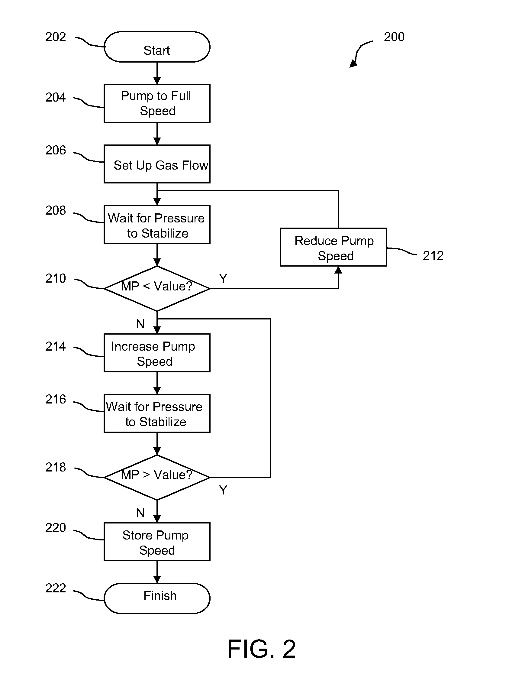
An apparatus for tuning pump speed at an optimal or desired speed using an automated method is disclosed. The apparatus includes a vacuum pump connected to a chamber for evacuating gas from the chamber. A sensor measures one or more characteristics, such as pressure, of the gas in the chamber. The measured characteristic is compared to a predetermined value. The speed of vacuum pump is adjusted based on the comparison until it falls in a desired range.

Description

BACKGROUND OF THE INVENTION[0001]The present invention relates generally to an apparatus and method for tuning a rotational speed of vacuum pump using an automated control scheme.[0002]A vacuum pump is a device for evacuating gas from an enclosed space in order to create a low pressure environment within the space. It is often used in a semiconductor manufacturing process. For example, one or more vacuum pumps can be used to evacuate the gas in a process chamber during a chemical vapor deposition (CVD) process. As another example, the vacuum pump can be used to create a low pressure environment in a load lock chamber interfacing between a process chamber and ambient environment. Examples of vacuum pumps categorized by their functions in a semiconductor manufacturing process include, without limitation, booster pumps, load lock pumps, and backing pumps.[0003]Conventionally, a vacuum pump is often over specified to accommodate many variables for different applications, in order to pro...

Claims


Application Information

Patent Timeline
IPC IPC(8): F04B49/00
CPCF04B37/14F04B2201/1201F04B49/20F04B49/08F04B2207/02F04B49/00F04B49/06F05B2210/12Y10S417/00Y10S415/00
Inventor SHELLEY, GERALD ROBINROMEO, MARK KOLLINSCHWAB, JEFFREY ROBERT
Owner EDWARDS LTD
Learn More