
Contour Alignment For Model Calibration

a technology of contour alignment and model calibration, applied in the field of calibration of models, can solve the problems of small feature size, difficult to faithfully reproduce the image, and reduced feature size, and achieve the effect of improving the model

Active Publication Date: 2011-08-18
SIEMENS PROD LIFECYCLE MANAGEMENT SOFTWARE INC
View PDF4 Cites 27 Cited by
  • Summary
  • Abstract
  • Description
  • Claims
  • Application Information

AI Technical Summary

Problems solved by technology

This reduction in feature size increases the difficulty of faithfully reproducing the image intended by the layout design onto the substrate.
Adding to the difficulty associated with increasingly smaller feature size is the diffractive effects of light.
These effects often result in defects where the intended image is not accurately “printed” onto the substrate during the photolithographic process, creating flaws in the manufactured device.
When the simulated printed image cannot be substantially improved by further displacement of the edge segments, it is often said that the optical proximity correction process has converged.
Layout designs can be very large.
Accordingly, performing even a single iteration of an optical proximity correction process on a design is computationally intensive.
Due to the number of required iterations of optical proximity correction and the complexity and size of modern layout designs, the time required to perform optical proximity correction is often measured in days.
Even where advanced computer processing techniques are employed, performing model-based optical proximity correction may still take days.
If the model is not accurate, then the corrected design data may still not print the desired image during the actual photolithographic manufacturing process.
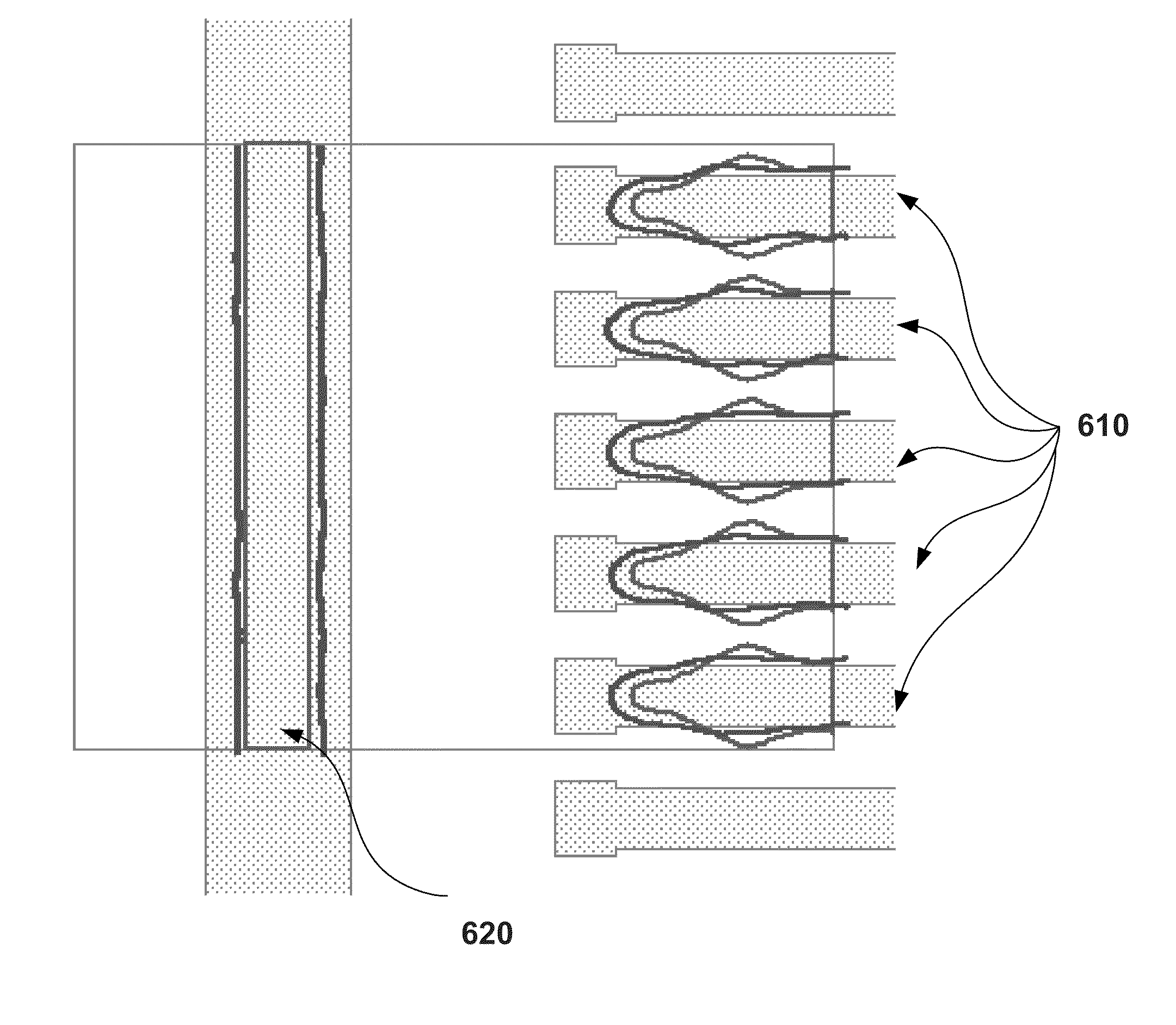
One of the primary metrology challenges in contour-based calibration is to properly import and overlay the measured physical contours (or measurement contours) onto the corresponding calibration features for the comparison.
Thus, contour-based calibration is sensitive to input misalignment of the measured contour data.
However, design features are not always printable on a wafer, and hence aligning SEM measured contours to the original layout design data is not always straightforward.

Method used


Image

  • Contour Alignment For Model Calibration
  • Contour Alignment For Model Calibration
  • Contour Alignment For Model Calibration

Examples


Embodiment Construction

Optical Proximity Correction

[0037]In a photolithographic process, as explained above, electromagnetic radiation is transmitted through selectively transparent areas of a mask. The radiation passing through these transparent areas then irradiates desired portions of a layer of photoresistive material on a semiconductor substrate. The mask in turn is created from layout design data describing the geometric features that should be manufactured on the semiconductor substrate in order to create the desired circuit. For example, if a transistor should have a rectangular gate region, then the layout design data will include a rectangle defining that gate region. This rectangle in the layout design data is then implemented in a mask for creating the rectangular gate region.

[0038]During a photolithographic process, however, optical effects will prevent the shapes defined by the mask from being faithfully imaged onto the substrate. Diffractive effects, for example, may distort the image produ...


PUM


Abstract

Techniques for model calibration and alignment of measurement contours of printed layout features with simulation contours obtained with a model are disclosed. With various implementations of the invention, contour point errors are determined. Based on the contour point errors and a cost function, values of alignment parameters may be determined. The values of alignment parameters may be used to realign the measurement contours for model calibration. The alignment may be conducted concurrently with model calibration.

Description

RELATED APPLICATIONS[0001]This application claims priority to U.S. Provisional Patent Application No. 61 / 304,807, entitled “Contour Self-Alignment For OPC Model Calibration,” filed on Feb. 16, 2010, and naming Ir Kusnadi et al. as inventors, which application is incorporated entirely herein by reference.[0002]This application also claims priority to U.S. patent application Ser. No. 13 / 029,113, entitled “Contour Self-Alignment For Optical Proximity Correction Model Calibration,” filed on Feb. 16, 2011, and naming Ir Kusnadi et al. as inventors, which application is incorporated entirely herein by reference.FIELD OF THE INVENTION[0003]The present invention is directed to the calibration of models used to simulate lithographic processes. Various implementations of the invention may be particularly beneficial to the model calibration based on contours of printed layout features.BACKGROUND OF THE INVENTION[0004]Electronic circuits, such as integrated microcircuits, are used in a variety ...

Claims


Application Information

Patent Timeline
Patent Type & Authority Applications(United States)
IPC IPC(8): G06F9/455
CPCG03F7/70441G03F7/70516G03F7/705
Inventor KUSNADI, IRDO, THUY Q.GRANIK, YURISTURTEVANT, JOHN L.
Owner SIEMENS PROD LIFECYCLE MANAGEMENT SOFTWARE INC
Learn More