Engine Vacuum System

Inactive Publication Date: 2011-08-25
FORD GLOBAL TECH LLC
View PDF16 Cites 14 Cited by
  • Summary
  • Abstract
  • Description
  • Claims
  • Application Information

AI Technical Summary

Benefits of technology

[0003]The inventors herein have recognized the above disadvantages and have developed a system that can improve vacuum actuator performance. In one example, a vacuum system for a vehicle is provided where the vacuum system includes a vacuum pump; a brake booster in pneumatic communication with the vacuum pump via a check valve; a wastegate va

Problems solved by technology

Therefore, it may be difficult to control vacuum op

Method used


Image

  • Engine Vacuum System
  • Engine Vacuum System
  • Engine Vacuum System

Examples


Embodiment Construction

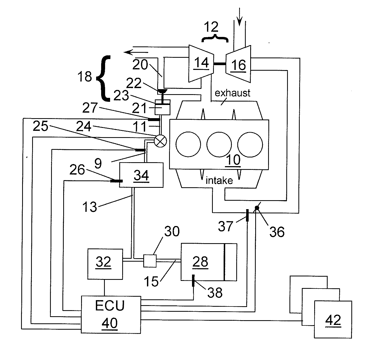
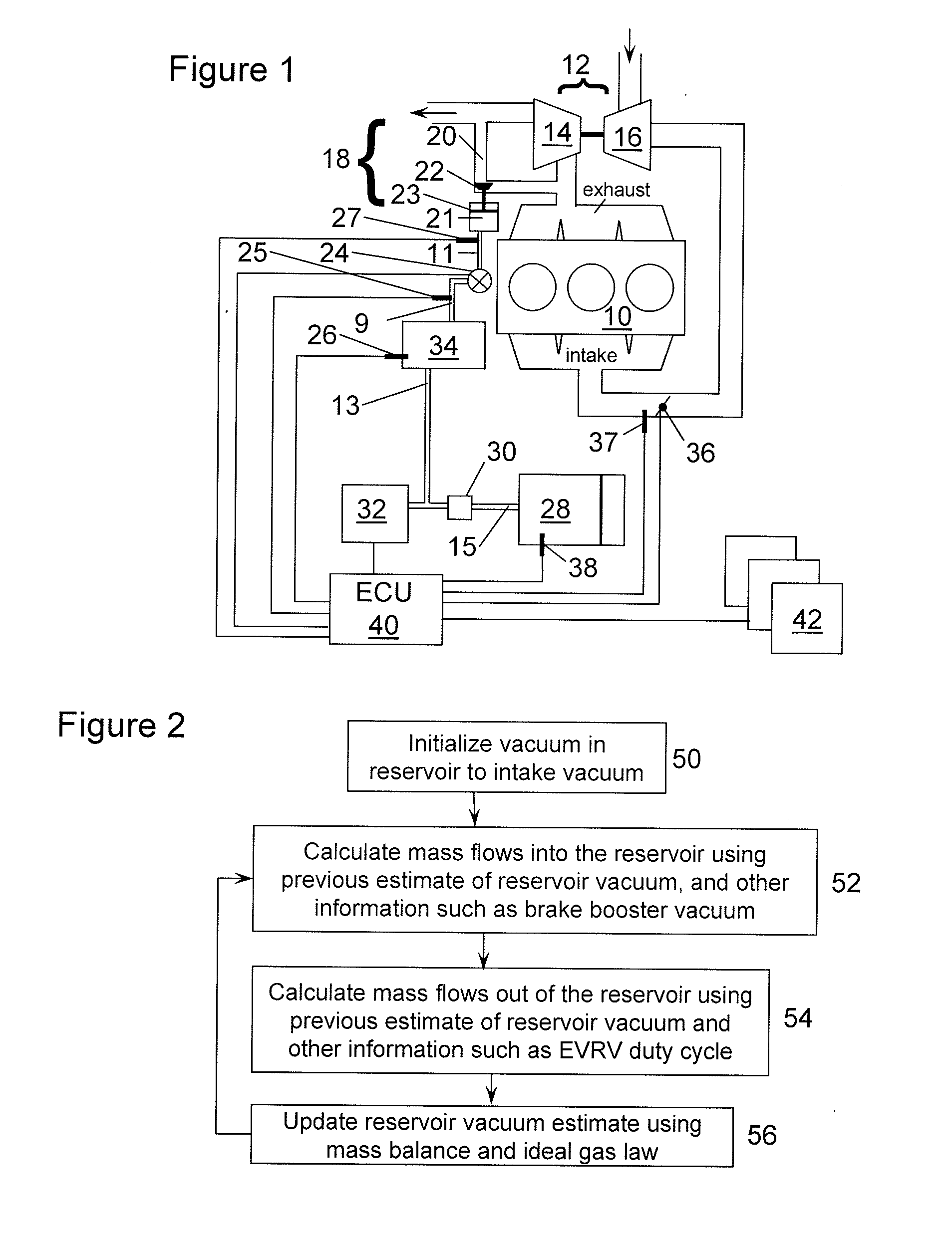
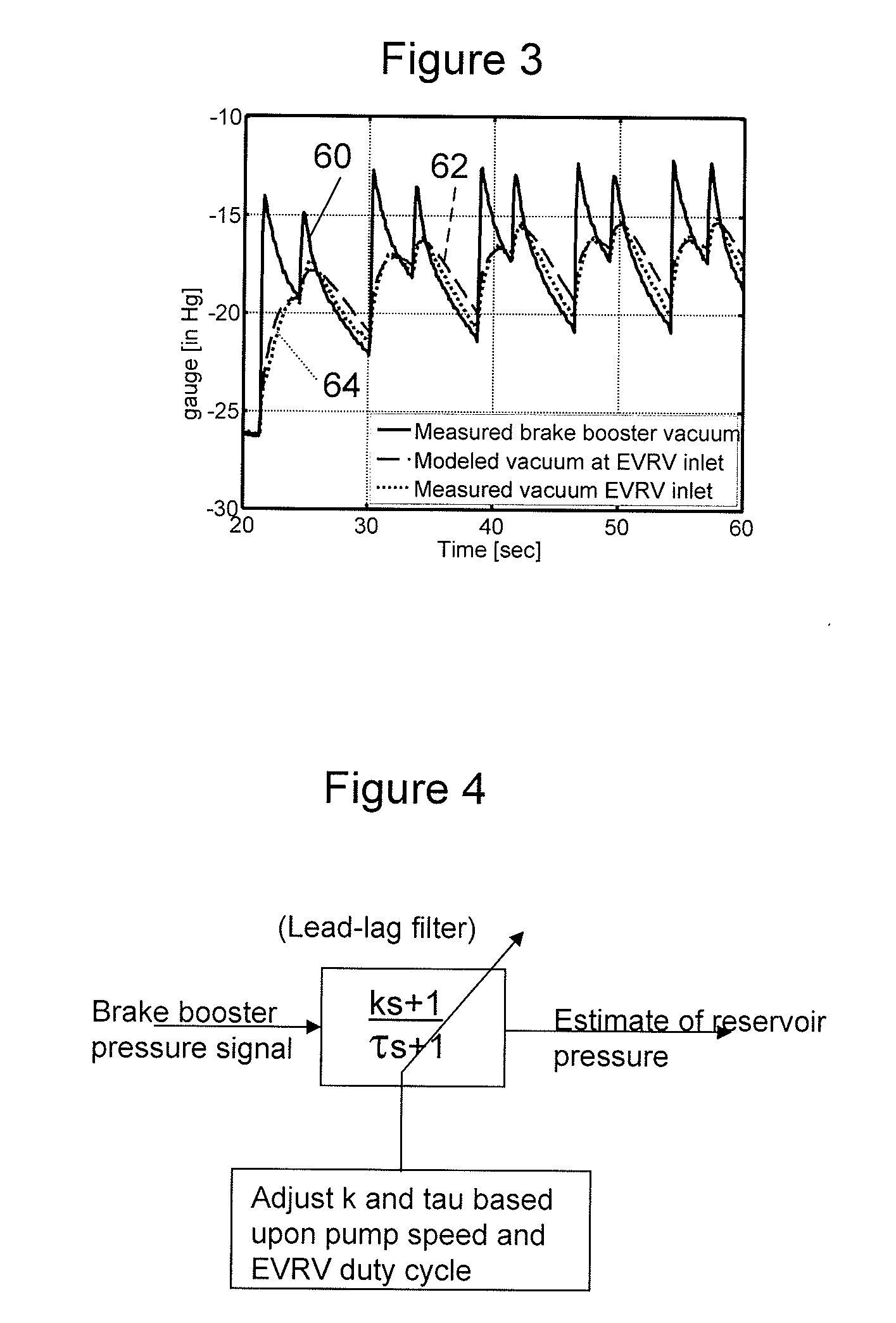
[0014]The present description is related to controlling a wastegate of a turbocharged engine. FIG. 1 shows one example of a boosted engine where the methods of FIGS. 2, 4, 5 and 6 may be applied. FIG. 3 shows a comparison of actual and estimated vacuum levels at a vacuum inlet port of an EVRV when a vacuum level at a brake booster in pneumatic communication with the EVRV changes. FIGS. 2, 4, 5, and 6 show example flowcharts for operating a vacuum operated turbocharger wastegate.

[0015]A vacuum pump can be provided onboard a vehicle for brake assist and for vacuum controlled valves, such as to control a wastegate coupled to a turbocharger. Rather than provide a vacuum pump for each device, one vacuum pump can be provided. It is useful for the vacuum level at the vacuum inlet port of the vacuum-operated valves to be known so that the valves can be controlled to a desired position or setting. Further, by knowing the vacuum level at the inlet port of the vacuum-operated valve, it is poss...


PUM


Abstract

A vacuum pump onboard a vehicle provides vacuum for a brake booster and to control the electronic vacuum regulation valve (EVRV) valve of a wastegate on a turbocharger. Commands to the EVRV are based on an operating condition of an engine and the vacuum level in the vacuum system. In one example, a vacuum sensor is provided to determine vacuum proximate the EVRV. In another example, the vacuum proximate the EVRV is modeled based on the vacuum at the brake booster, which may be determined by a vacuum sensor coupled to the brake booster.

Description

TECHNICAL FIELD[0001]The present disclosure relates to providing vacuum for a vehicle vacuum system and using the vacuum for control and brake assist purposes.BACKGROUND[0002]Brake assist systems and turbocharger wastegates are just two examples of devices that may be vacuum operated. The ability to provide brake assist and to control the vacuum operated wastegate as desired depends on there being a sufficient amount of vacuum in the vacuum system as well as knowledge of the vacuum level. However, the level of vacuum within the vacuum system may vary depending on vehicle operating conditions. Therefore, it may be difficult to control vacuum operated devices with a desired level of consistency.SUMMARY[0003]The inventors herein have recognized the above disadvantages and have developed a system that can improve vacuum actuator performance. In one example, a vacuum system for a vehicle is provided where the vacuum system includes a vacuum pump; a brake booster in pneumatic communicatio...

Claims


Application Information

Patent Timeline
IPC IPC(8): B60T13/57F15D1/00
CPCB60T13/52Y10T137/0318
Inventor KARNIK, AMEY Y.ZAITZ, MICHAEL JOSEPHBUCKLAND, JULIA HELENCUNNINGHAM, RALPH WAYNE
Owner FORD GLOBAL TECH LLC
Why Eureka
Try Eureka