
Piezoelectric coagulation sensors

a technology of coagulation sensor and piezoelectric technology, applied in the direction of instruments, diagnostic recording/measuring, specific gravity measurement, etc., can solve the problems of incompatibility, difficult or expensive design manufacturing, and excessive sample siz

Active Publication Date: 2011-08-25
MICROPOINT BIOTECHNOLOGIES CO LTD
View PDF7 Cites 25 Cited by
  • Summary
  • Abstract
  • Description
  • Claims
  • Application Information

AI Technical Summary

Benefits of technology

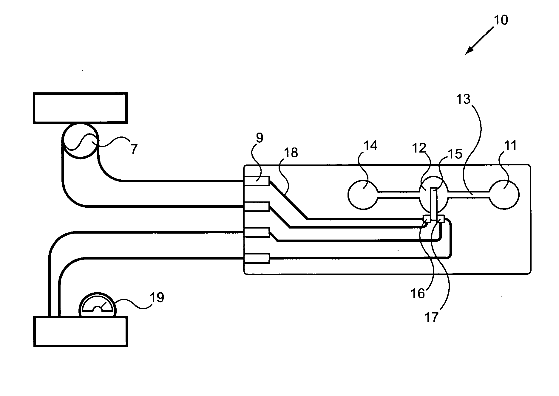
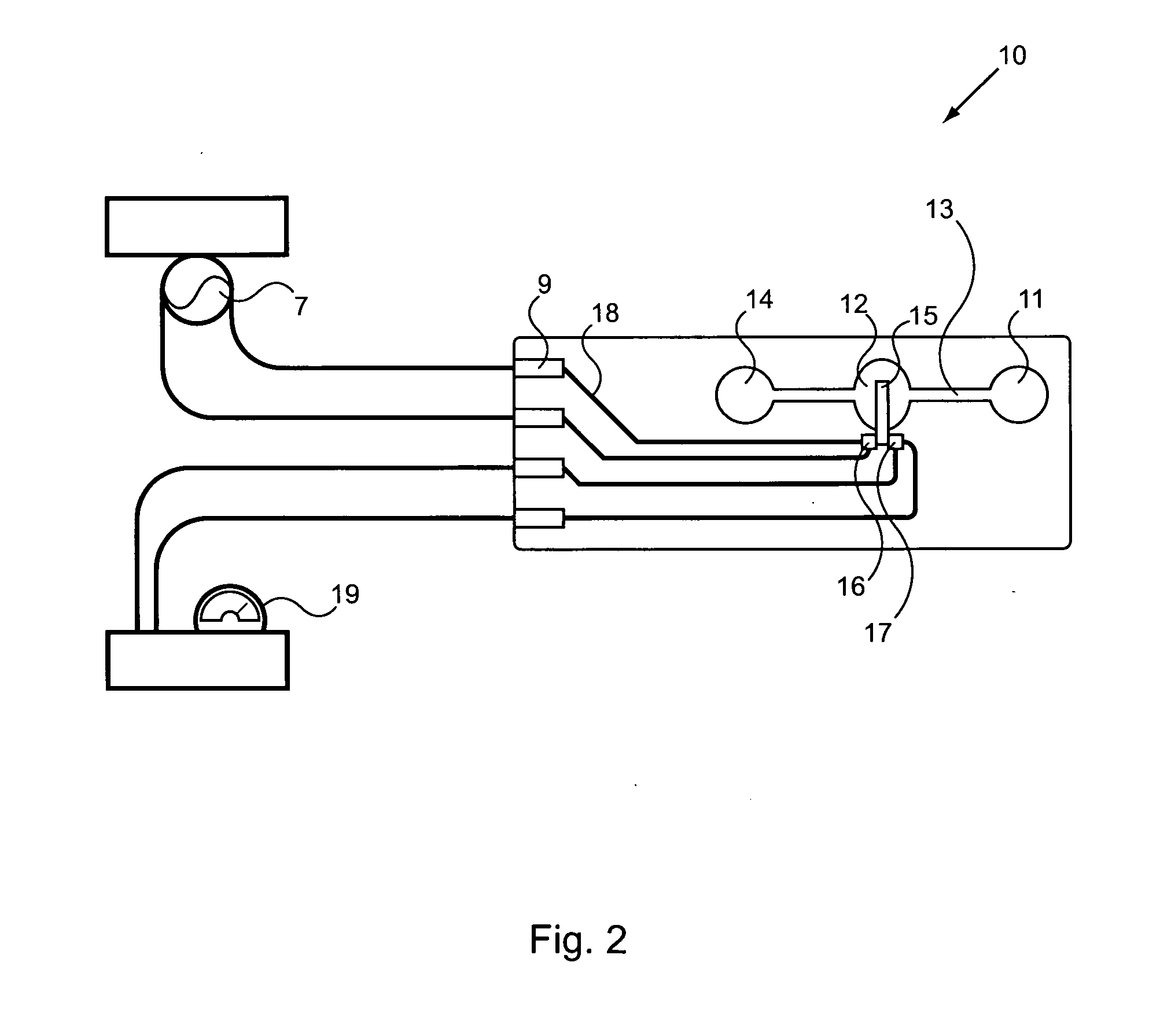
[0017]Working members can provide leverage and working surface area advantages, while isolating the sample from contact with the transducers. The working members can be any suitable shape, e.g., for a particular combination of sample, transducer and sample chamber. In an embodiment, the working member is in functional contact with the transducer at a mounting surface, and most of the sample contact surface is not in a plane parallel to the mounting surface (e.g., the working member is a beam cantilevered into the sample chamber or has a dome shape). In some embodiments, the working member is a cantilevered beam in contact with the transducer at one end but not at the opposite end.

Problems solved by technology

However, many of these designs are difficult or expensive to manufacture, or are not compatible with at a micro-scale designs for testing of very small samples.
In addition the required sample size can be excessive, especially considering the required redundant and confirmatory retesting.
However, such a device is hard to manufacture and operate at a micro-scale.
Such a device requires direct contact of the sample with the piezo film and its associated electrodes, or provision of additional insulator layers that can interfere with the sensitivity of the device.
The mass of the sensor (typically, a quartz crystal) relative to the sample can also reduce the sensitivity of the device.

Method used


Image

  • Piezoelectric coagulation sensors
  • Piezoelectric coagulation sensors
  • Piezoelectric coagulation sensors

Examples


examples

[0093]The following examples are offered to illustrate, but not to limit the claimed invention.

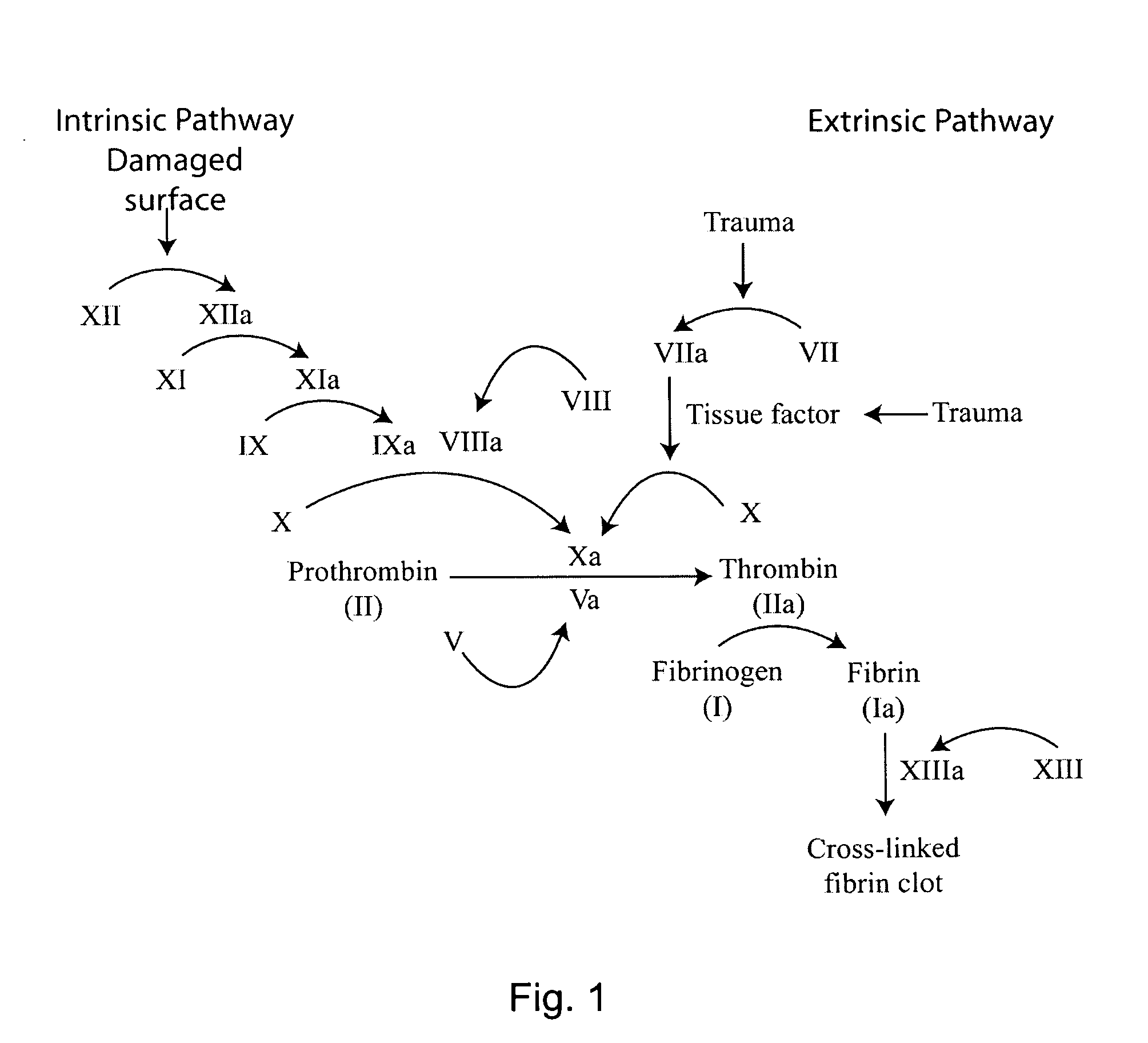
[0094]The prothrombin time (PT) measures the function of the coagulation extrinsic pathway. In a clinical setting, the PT is used to determine the clotting tendency of blood, monitor warfarin dosage, to detect liver disease, and can suggest a vitamin K deficiency. The normal range for prothrombin time is usually around 12-15 seconds

[0095]In a standard PT assay time, blood is drawn into a test tube containing liquid citrate, which acts as an anticoagulant by binding the calcium in a sample. The blood is mixed, then centrifuged to separate blood cells from plasma. An excess of calcium is added (thereby reversing the effects of citrate), along with tissue factor (also known as factor III or thromboplastin). The time the sample takes to clot at 37° C. is traditionally detected mechanically or optically.

[0096]A PT can be determined using the methods and devices of the present invention. For exa...


PUM

PropertyMeasurementUnit
diameteraaaaaaaaaa
thicknessaaaaaaaaaa
thicknessaaaaaaaaaa

Abstract

This invention provides methods and devices to measure physical characteristics of sample fluids. Samples are introduced into a sample chamber in contact with a mechanically oscillating working member. The vibrations are received by a piezoelectric sensor transducer and correlated to a sample characteristic, such as viscosity or density. The devices include a sample chamber in contact with one or more working members actuated by a piezoelectric actuator and / or monitored by a piezoelectric sensor.

Description

CROSS-REFERENCE TO RELATED APPLICATIONS[0001]This application claims priority to and benefit of a prior U.S. Provisional Application No. 61 / 279,542, Piezoelectric Coagulation Sensors, by Michael Huang, et al., filed Oct. 21, 2009. The full disclosure of the prior application is incorporated herein by reference.FIELD OF THE INVENTION[0002]The present inventions are directed to piezoelectric detectors and methods of detecting, e.g., physical properties of a fluid using piezoelectric devices. An energized piezoelectric transducer can contact a sample to determine, e.g., the mass, density or viscosity of the sample through correlation with a resultant vibrational frequency. A sample can be brought into contact with a piezoelectric transducer providing a physical waveform. The waveform can be detected and correlated with a physical characteristic of the sample.BACKGROUND OF THE INVENTION[0003]Piezoelectric devices are used in various detector systems, e.g., to detect the presence of spec...

Claims


Application Information

Patent Timeline
Patent Type & Authority Applications(United States)
IPC IPC(8): G01N9/00G01N29/02G01N11/16G01G9/00
CPCA61B5/02035G01N33/4905A61B5/145
Inventor HUANG, MICHAELWU, MENGYAWU, MENGYOU
Owner MICROPOINT BIOTECHNOLOGIES CO LTD
Learn More