Light source device and projection type display apparatus
- Summary
- Abstract
- Description
- Claims
- Application Information
AI Technical Summary
Benefits of technology
Problems solved by technology
Method used
Image
Examples
first embodiment
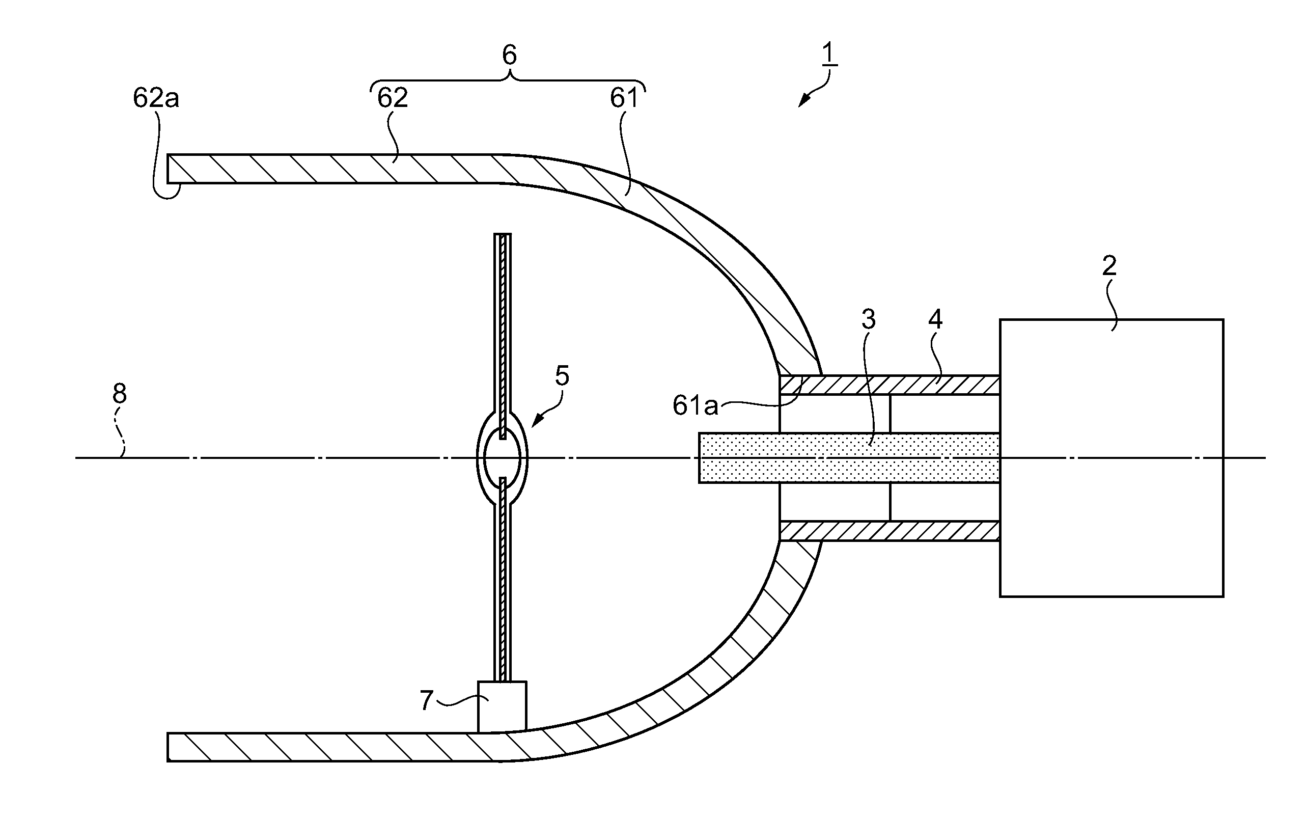
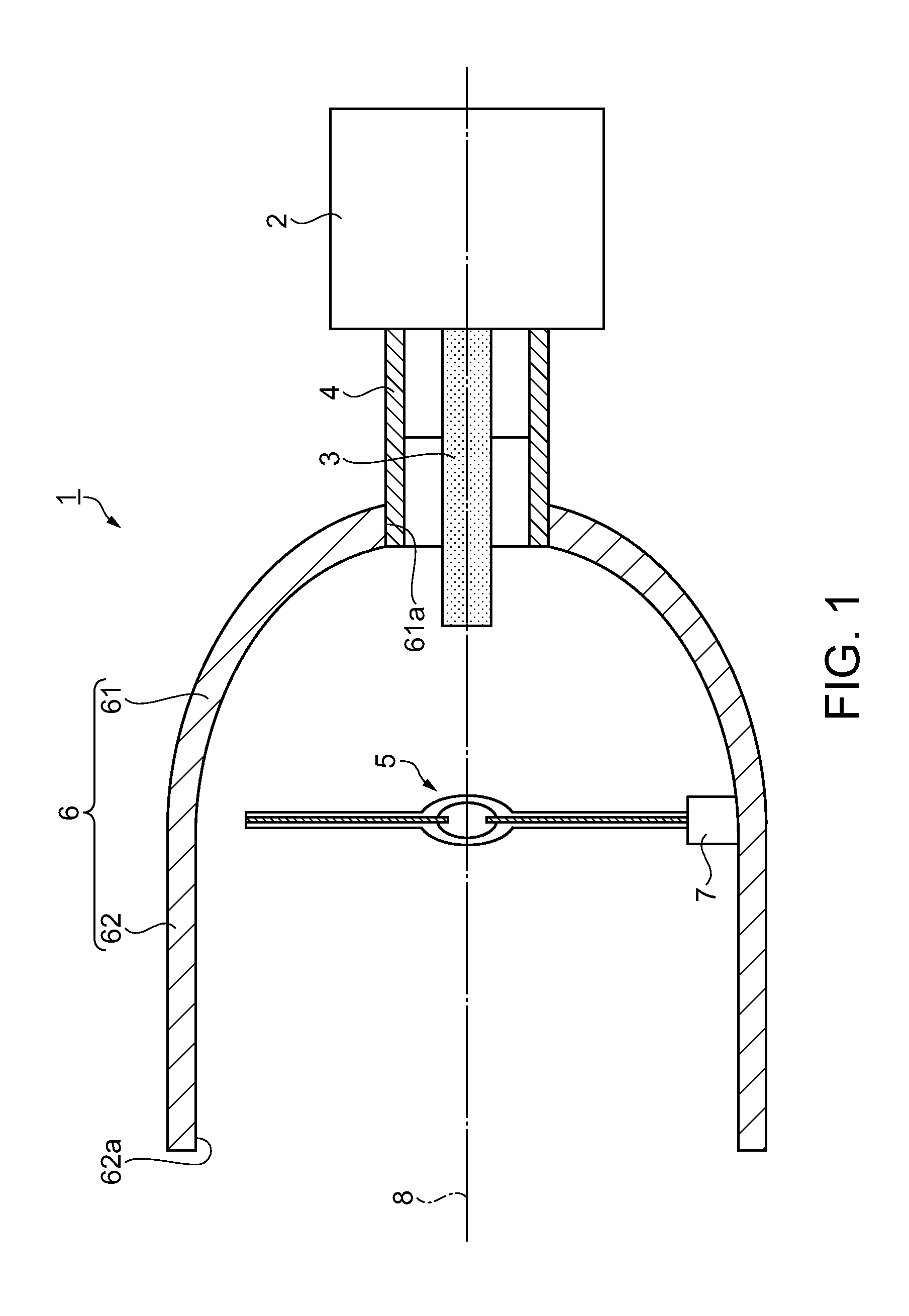
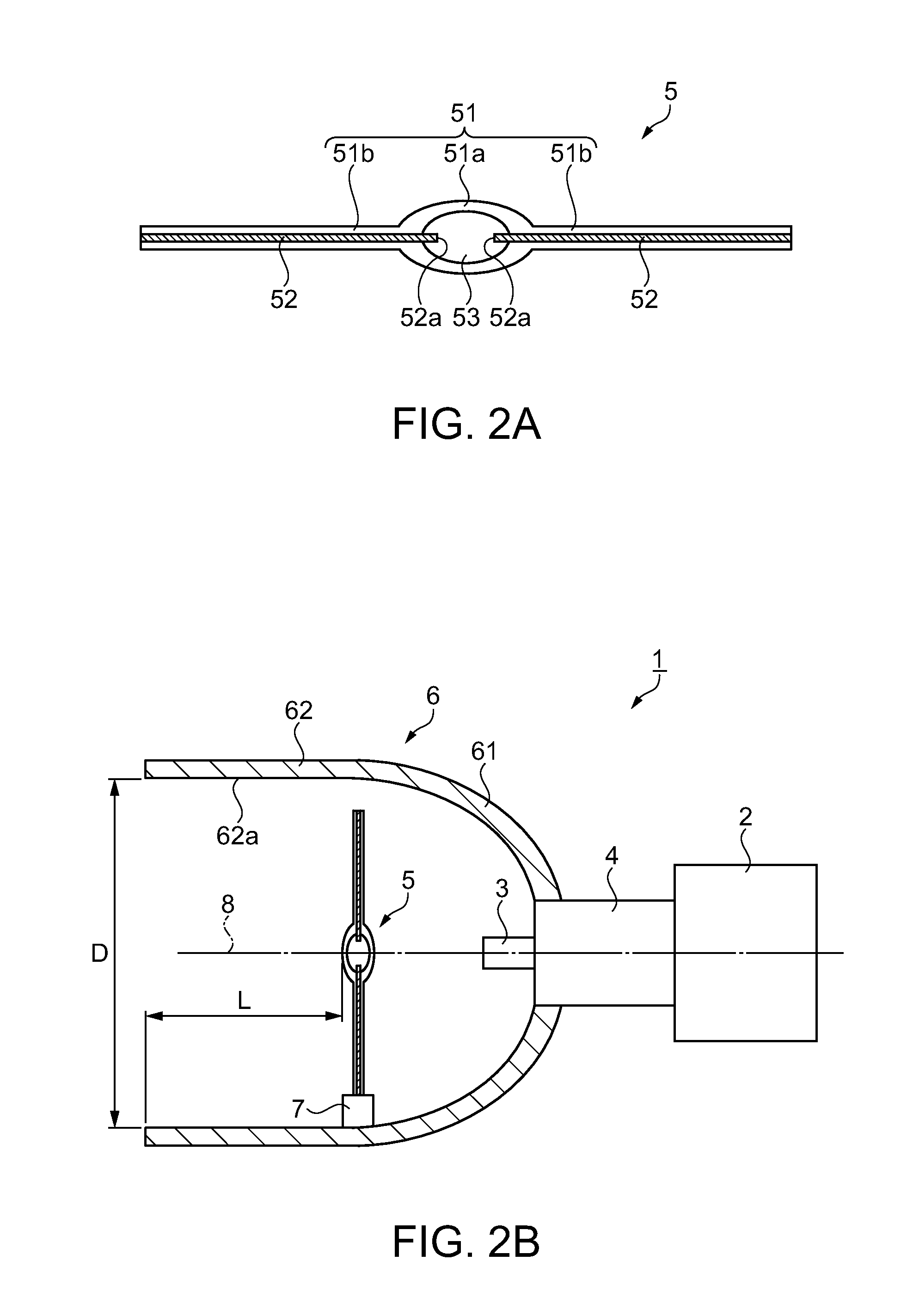
[0027]FIG. 1 is a cross-sectional view illustrating the structure of a light source device according to a first embodiment. As illustrated in FIG. 1, a light source device 1 includes a microwave power source 2 which generates microwaves, a central conductor 3 extended from the interior of the microwave power source 2 to radiate the microwaves generated by the microwave power source 2, a coaxial pipe 4 which accommodates the central conductor 3 as an inside conductor, a discharge lamp (light emitter) 5 disposed on the side opposite to the microwave power source 2 with respect to the central conductor 3 to emit light by power supply produced by the microwaves radiated from the central conductor 3, a reflector 6 which has an opening (aperture) 62a at one end to reflect lights received from the discharge lamp 5 disposed inside the reflector 6 toward the opening 62a, and a holding member 7 which holds the discharge lamp 5 on the reflector 6. The microwave power source 2, the central cond...
second embodiment
[0044]A light source device according to a second embodiment as another example is now described. FIG. 3 is a cross-sectional view illustrating the structure of the light source device in the second embodiment. FIG. 4 is a cross-sectional view illustrating the structure of a discharge lamp in the second embodiment. A light source device 10 according to the second embodiment is different from the light source device 1 in the first embodiment only in the holding structure of a holding member 15 for supporting a discharge lamp 9 in FIG. 3 and the positioning structure for positioning conductors 92 on a sealing portion 91a in FIG. 4. Thus, components of the light source device 10 other than the discharge lamp 9 and the holding member 15 are similar to the corresponding components in the first embodiment, and the same reference numbers are given to the components shown in FIGS. 3 and 4 similar to the corresponding components in the first embodiment. According to the light source device 1...
modified example 1
[0061]According to the light source device 1, each of the conductors 52 of the discharge lamp 5 has one end inserted into the sealing portion 51a, and is insulated from the reflector 6. However, one or both of the conductors 52 of the discharge lamp5 may have conduction with the reflector 6. The conductor 52 of the discharge lamp 5 is not required to be provided on both sides of the sealing portion 51a but may be disposed only one side of the sealing portion 51a and insulated from the reflector 6. Alternatively, the conductor 52 provided only on one side may have conduction with the reflector 6. As in this example, the structure of the light source device 1 may have a wide variety of options selected according to the shape of the reflector 6, the light emitting substances 53 of the discharge lamp 5 and the like. Accordingly, the light source device 1 having the optimum structure can be produced.
PUM
 Abstract
Description
Claims
Application Information
 - R&D
- Intellectual Property
- Life Sciences
- Materials
- Tech Scout
- Unparalleled Data Quality
- Higher Quality Content
- 60% Fewer Hallucinations
Browse by: Latest US Patents, China's latest patents, Technical Efficacy Thesaurus, Application Domain, Technology Topic, Popular Technical Reports.
© 2025 PatSnap. All rights reserved.Legal|Privacy policy|Modern Slavery Act Transparency Statement|Sitemap|About US| Contact US: help@patsnap.com


