Liquid crystal display device and electronic device

a liquid crystal display and electronic device technology, applied in the direction of electric digital data processing, instruments, computing, etc., can solve the problems of insufficient reduction of power consumption of liquid crystal display devices, inability to keep the voltage between pixel electrodes and common electrodes constant in some cases, so as to reduce the deterioration of image quality, reduce the refresh rate, and reduce the effect of power consumption

Active Publication Date: 2011-08-25
SEMICON ENERGY LAB CO LTD
View PDF99 Cites 43 Cited by
  • Summary
  • Abstract
  • Description
  • Claims
  • Application Information

AI Technical Summary

Benefits of technology

[0018]According to one embodiment of the present invention, it is possible to reduce deterioration of image quality due to change in gray level when a still image is displayed with a reduced refresh rate. In addition, power consumption can be reduced by a reduction in refresh rate at the time of displaying a still image.

Problems solved by technology

However, a voltage between a pixel electrode and a common electrode cannot be kept constant in some cases because the potential of the pixel electrode is changed by the off-state current of a pixel transistor and / or leakage current from liquid crystals.
As a result, a voltage applied to the liquid crystals is changed, so that a desired gray level cannot be obtained and the quality of a displayed image deteriorates.
Thus, power consumption of a liquid crystal display device cannot be sufficiently reduced by the reduction in refresh rate.

Method used


Image

  • Liquid crystal display device and electronic device
  • Liquid crystal display device and electronic device
  • Liquid crystal display device and electronic device

Examples


embodiment 1

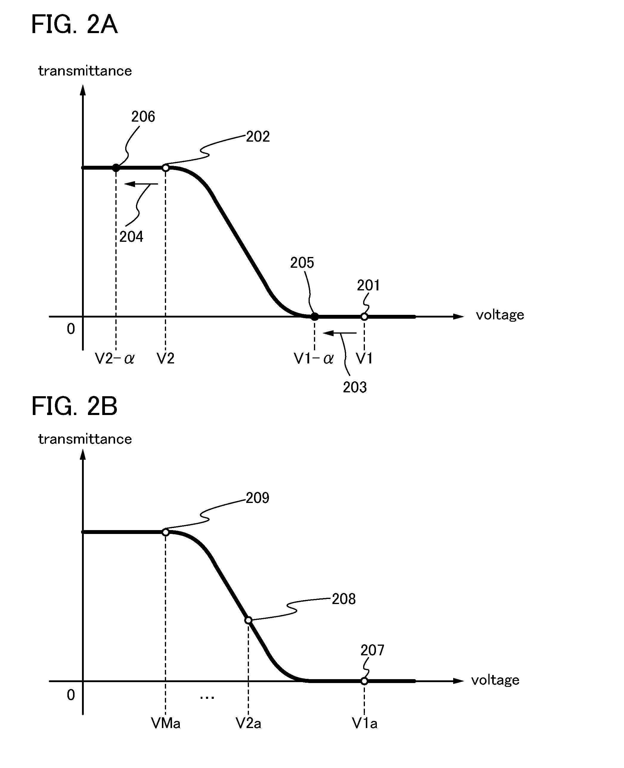
[0039]In this embodiment, a liquid crystal display device will be described with reference to a schematic diagram, a block diagram, and a diagram showing the relation between the transmittance of a liquid crystal element and an applied voltage.

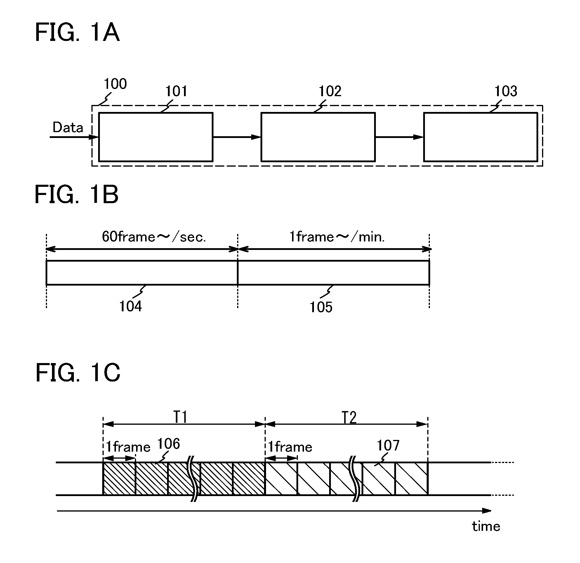
[0040]First, a liquid crystal display device according to this specification will be described with reference to FIGS. 1A to 1C illustrating a simple block diagram of the liquid crystal display device and schematic diagrams for explaining the liquid crystal display device.

[0041]A liquid crystal display device 100 illustrated in FIG. 1A includes a timing controller (also referred to as a timing control circuit) 101, a driver circuit 102, and a display portion 103. An image signal Data is supplied to the timing controller 101 from the outside.

[0042]The timing controller 101 in FIG. 1A has a function of converting the absolute value of a voltage applied to a liquid crystal element in accordance with the number of gray levels of the image signal D...

embodiment 2

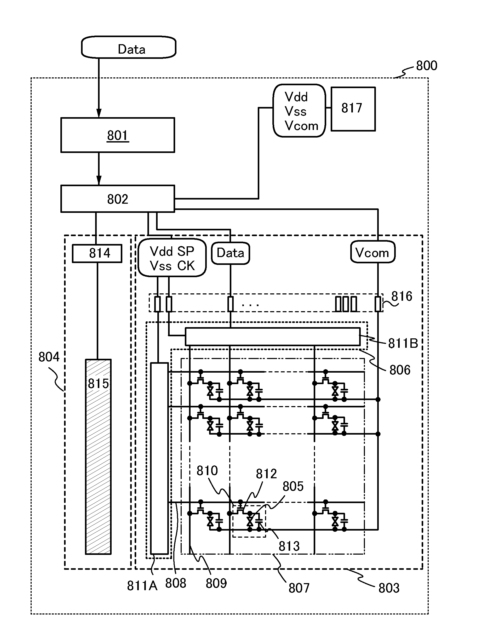
[0072]In this embodiment, a liquid crystal display device of the present invention and an embodiment of a liquid crystal display device with lower power consumption will be described with reference to FIG. 7, FIG. 8, FIGS. 9A and 9B, and FIG. 10.

[0073]The block diagram in FIG. 7 illustrates components in a liquid crystal display device 800 described in this embodiment. The liquid crystal display device 800 includes an image processing circuit 801, a timing controller 802, and a display panel 803. In the case where the liquid crystal display device 800 is a transmissive liquid crystal display device or a transflective liquid crystal display device, a backlight unit 804 is provided as a light source.

[0074]An image signal (an image signal Data) is supplied to the liquid crystal display device 800 from an external device connected thereto. Power supply potentials (a high power supply potential Vdd, a low power supply potential Vss, and a common potential Vcom) are supplied when a power ...

embodiment 3

[0119]In this embodiment, an example of a transistor that can be applied to a liquid crystal display device disclosed in this specification will be described.

[0120]FIGS. 11A to 11D each illustrate an example of a cross-sectional structure of a transistor.

[0121]A transistor 1210 illustrated in FIG. 11A is a kind of bottom-gate transistor and is also called an inverted staggered transistor.

[0122]The transistor 1210 includes, over a substrate 1200 having an insulating surface, a gate electrode layer 1201, a gate insulating layer 1202, a semiconductor layer 1203, a source electrode layer 1205a, and a drain electrode layer 1205b. An insulating layer 1207 is provided to cover the transistor 1210 and be stacked over the semiconductor layer 1203. A protective insulating layer 1209 is provided over the insulating layer 1207.

[0123]A transistor 1220 illustrated in FIG. 11B has a kind of bottom-gate structure called a channel-protective type (channel-stop type) and is also referred to as an inv...


PUM


Abstract

To suppress deterioration of quality of a still image displayed with a reduced refresh rate. A liquid crystal display device includes a display portion that is controlled by a driver circuit and includes normally white mode (or normally black mode) liquid crystals, and a timing controller for controlling the driver circuit. The timing controller is supplied with an image signal for displaying a moving image and an image signal for displaying a still image. The absolute value of a voltage applied to the liquid crystals in order to express black (or white) in an image corresponding to the image signal for displaying the still image is larger than that of a voltage applied to the liquid crystals in order to express black (or white) in an image corresponding to the image signal for displaying the moving image.

Description

TECHNICAL FIELD[0001]The present invention relates to a liquid crystal display device, a method for driving a liquid crystal display device, and an electronic device including a liquid crystal display device.BACKGROUND ART[0002]Liquid crystal display devices are widely used in large display devices such as television sets and small display devices such as mobile phones. Higher value-added devices have been demanded and the development has progressed. In recent years, attention is attracted to the development of low power consumption liquid crystal display devices, in terms of the increase in interest in global environment and improvement in convenience of mobile devices.[0003]Non-Patent Document 1 discloses a structure in which the refresh rate at the time of displaying a moving image and that at the time of displaying a still image are different from each other in order to reduce power consumption of a liquid crystal display device. Moreover, Non-Patent Document 1 discloses a struc...

Claims


Application Information

Patent Timeline
Patent Type & Authority Applications(United States)
IPC IPC(8): G09G3/36G09G5/10
CPCG09G3/3648G09G3/3607G09G2320/103G09G3/3614G09G3/3655G09G3/3688G09G2320/0214G09G2320/0247G09G2310/0297G09G2310/06G09G2330/021G09G2320/043
Inventor UMEZAKI, ATSUSHIMIYAKE, HIROYUKI
Owner SEMICON ENERGY LAB CO LTD
Why Eureka
Try Eureka