
Debris shield for geocontainers, method of making, and method of use thereof

a geocontainer and debris shield technology, applied in the field of geocontainers, can solve the problems of vandalism damage to the geocontainer,

Inactive Publication Date: 2011-08-25
NICOLON CORP
View PDF33 Cites 24 Cited by
  • Summary
  • Abstract
  • Description
  • Claims
  • Application Information

AI Technical Summary

Benefits of technology

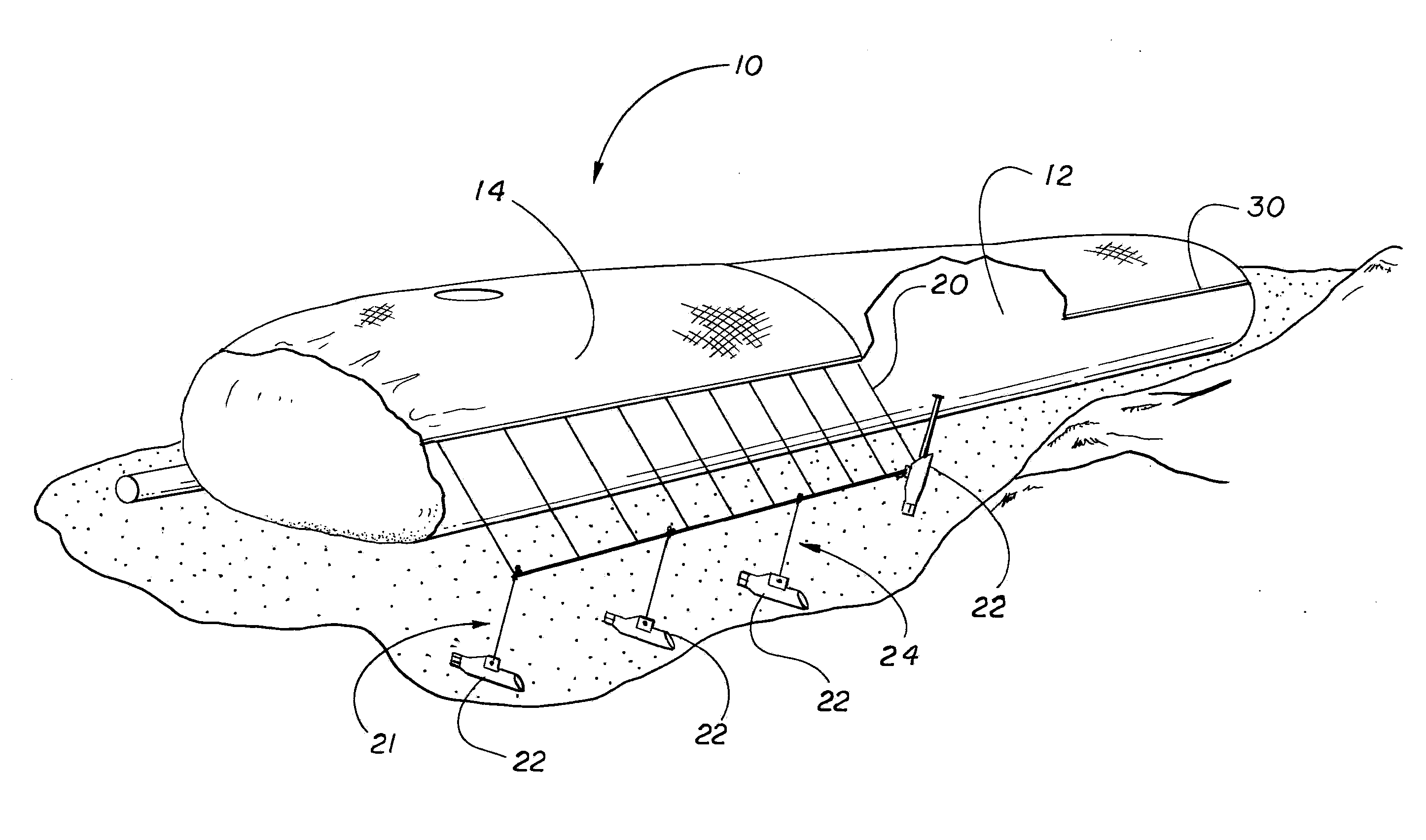
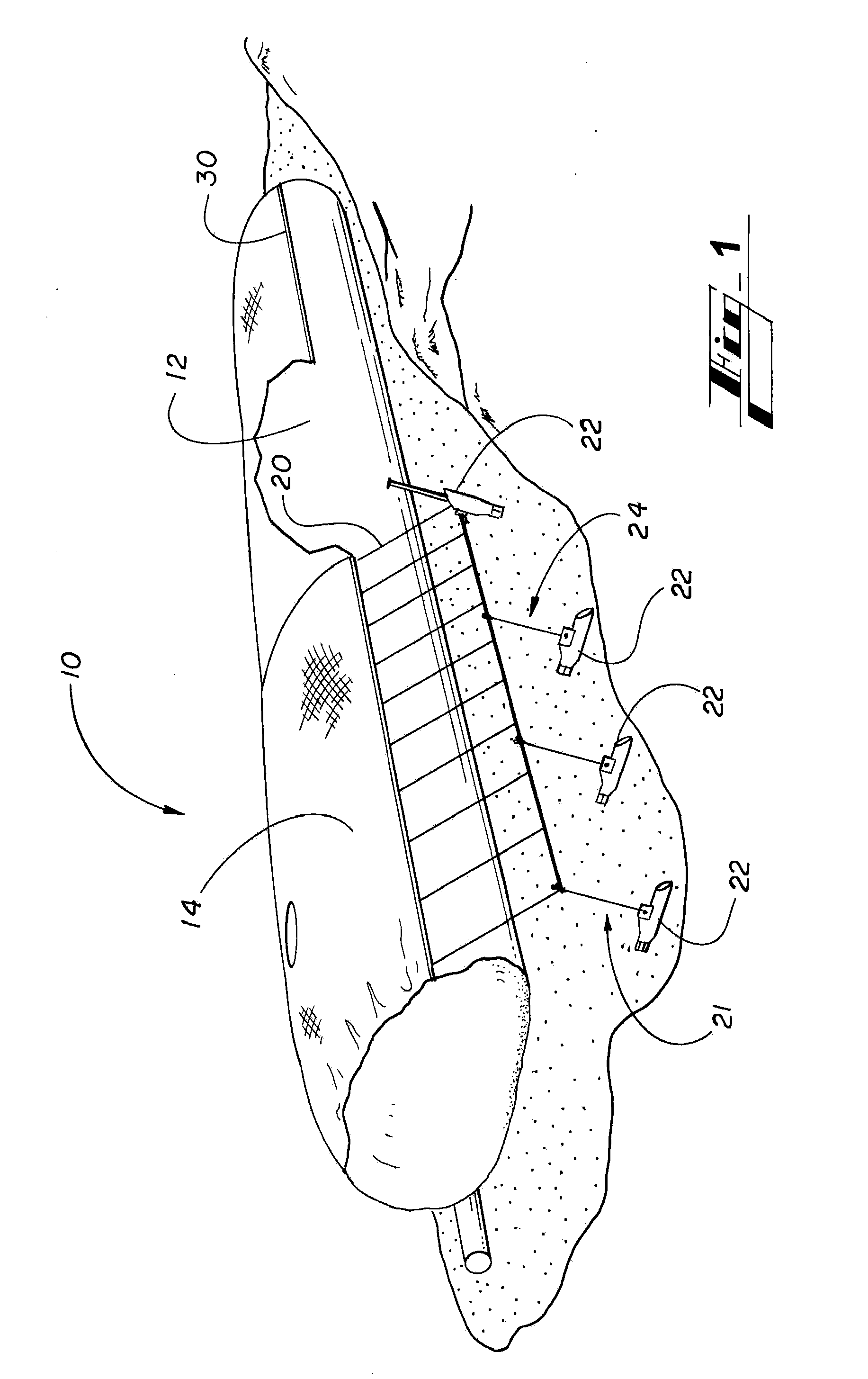
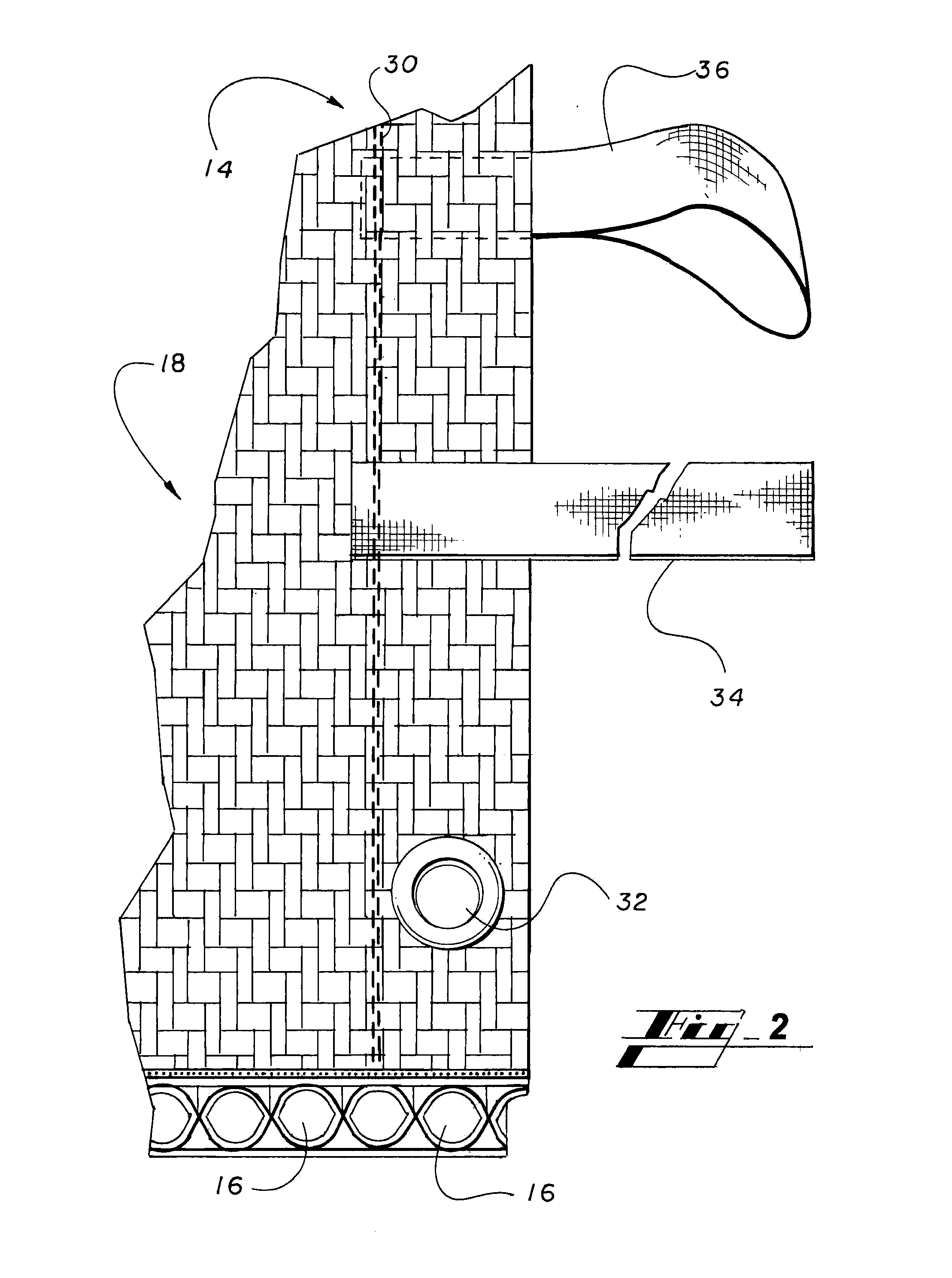
[0005]In accordance with the present invention, a debris shield is described herein which is employed to protect a geotextile container from damage often suffered as a result of high winds, rapid water, projectiles, vandalism and the like. The debris shield has at least two layers. One layer is an abrasion resistant woven fabric, and the other layer is a single-weave three-dimensional fabric having no more than about a 10% compression at a load of at least 20 pounds / inch2.

Problems solved by technology

However, such containers are subject to damage from debris that is carried by these bodies of water.
Often damage to the geocontainers occurs from inclement weather conditions, such as storms which generate heavy wind and / or seas.
Damage also occurs from vandalism, boat propellers, and a number of other situations.
When the integrity of the geocontainer is compromised or damaged, the geocontainer loses its ability to provide protection from erosion and other property damage.
Once an installed geotextile container is punctured, the sand reinforcing the geotextile container flows out, thereby compromising its performance.
Moreover, as waves hit the geotextile container, more and more sand escapes, and the geotextile container's height decreases.
As a result, soil erosion potential to the shoreline increases.

Method used


Image

  • Debris shield for geocontainers, method of making, and method of use thereof
  • Debris shield for geocontainers, method of making, and method of use thereof
  • Debris shield for geocontainers, method of making, and method of use thereof

Examples


example

[0062]Impact tests were conducted in accordance with ASTM Standards E1886 and E1196. The results are reported in Table 1 below. 11 test units consisting of 21 inch×21 inch square bags, having the appearance of a pillow, respectively containing approximately 100 pounds of sand (volume of sand was 1 cubic foot) were tested. Units 5-7 and 10 employed a debris shield made in accordance with the above description.

[0063]All three-dimensional layers of the debris shield were a plain 4-layer tubular weave having a thickness of about 625 mils. In the warp direction, non-shrink yarn was 20 mil round polypropylene and the shrink yarn was a 315 denier low density polyethylene round monofilament. Fill yarn was 565 denier round monofilament polypropylene.

[0064]All bags employed in the impact test were formed of a woven fabric of 11,000 denier polypropylene fibrillated warp yarns twisted at 1.5 tpi and 4600 denier polypropylene fibrillated fill yarns. The weave was a 2 / 2 twill, 3 pick per shed hav...


PUM

PropertyMeasurementUnit
Fractionaaaaaaaaaa
Fractionaaaaaaaaaa
Fractionaaaaaaaaaa

Abstract

Described herein is a protected container 10 employed to prevent soil erosion. The protected container is a geotextile container having a debris shield disposed thereon. The debris shield protects the integrity of the geotextile container by providing a strike barrier which has air and water flow capabilities. The debris shield is a composite fabric comprising a woven protective layer having abrasion resistance and a woven three-dimensional layer which provides impact dampening and energy dissipation.

Description

CROSS-REFERENCE TO RELATED APPLICATION[0001]This application claims benefit of U.S. Provisional Patent Application Ser. No. 61 / 306,215 filed Feb. 19, 2010, which is incorporated herein in its entirety by reference.TECHNICAL FIELD OF THE INVENTION[0002]The present invention relates generally to geocontainers employed to abate soil erosion. More specifically, the present invention is related to woven geotextile fabrics which absorb an impact force of a moving object and geocontainers employing such fabrics.BACKGROUND OF THE INVENTION[0003]Geotextile containers, also known as geocontainers, e.g., TenCate Geosynthetics North America's Geotube®, are employed to protect shorelines, rebuild beaches, and reclaim land from bodies of water. Typically, geocontainers are filled with sand or other soil and are placed above or within the soil of the land being protected. However, such containers are subject to damage from debris that is carried by these bodies of water.[0004]Often damage to the g...

Claims


Application Information

Patent Timeline
IPC IPC(8): E02B3/12D03D25/00D03D15/567
CPCD03D1/0041D10B2505/204D03D3/02D03D11/00D03D13/008D03D15/00D03D15/0083D03D15/04D10B2321/021D10B2321/022D10B2321/10D10B2331/02D10B2331/021D10B2331/061D10B2331/14D10B2331/301D10B2401/041D10B2401/22D03D1/007Y10T442/3504Y10T442/30Y10T442/3472D03D15/567D03D15/50D03D15/41D03D15/283E02D5/00E02B15/00D03D1/0043
Inventor JONES, DAVID MICHAELSPIKES, TOMMYTIMPSON, CHRIS
Owner NICOLON CORP
Learn More