Imprint apparatus, template of imprint apparatus, and article manufacturing method
a technology of imprint apparatus and template, applied in the field of imprint apparatus, can solve the problems of affecting the accuracy of imprint apparatus,
- Summary
- Abstract
- Description
- Claims
- Application Information
AI Technical Summary
Benefits of technology
Problems solved by technology
Method used
Image

Examples
first embodiment
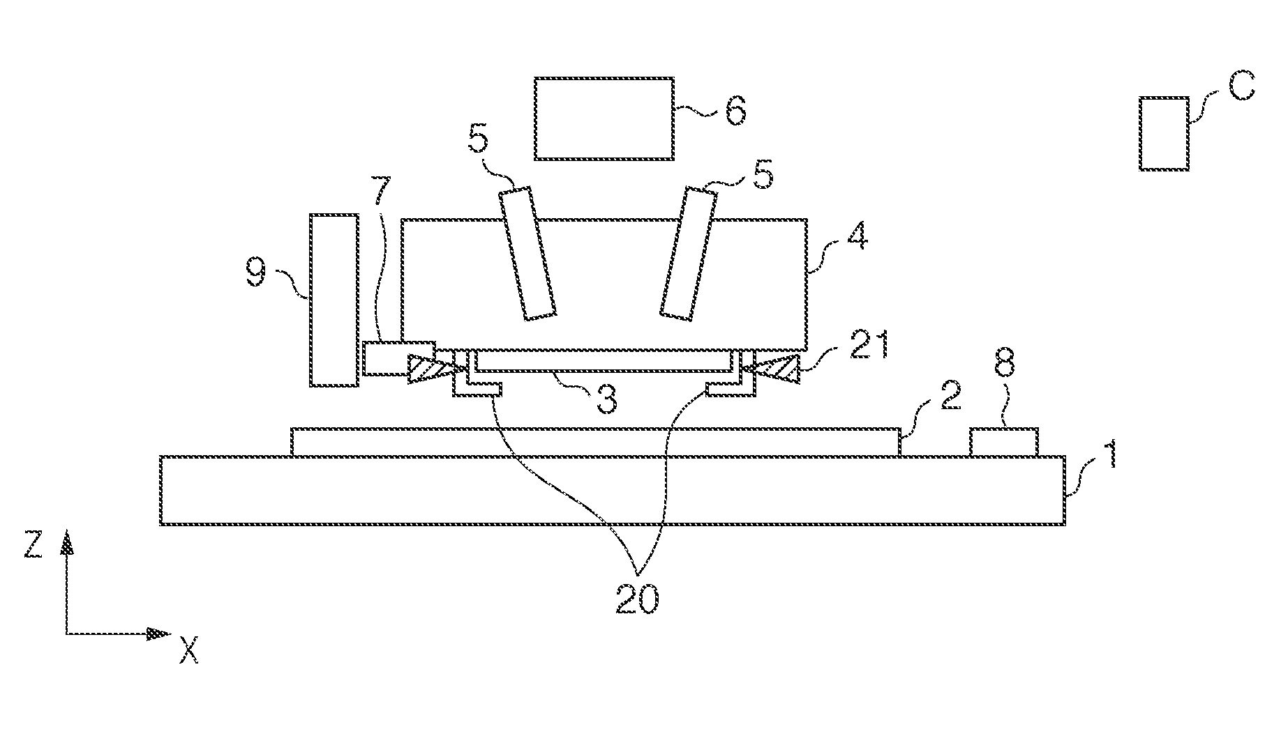
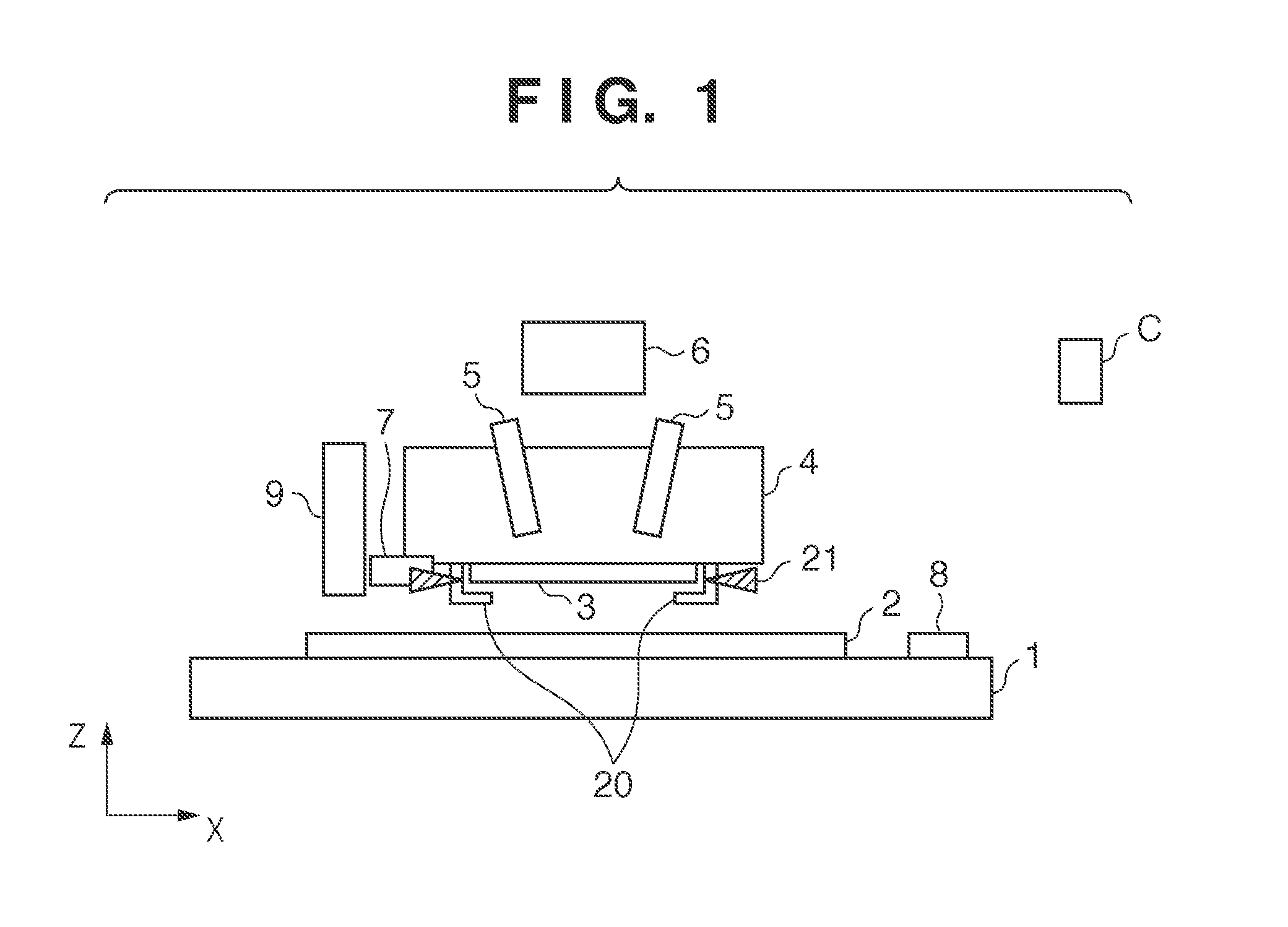
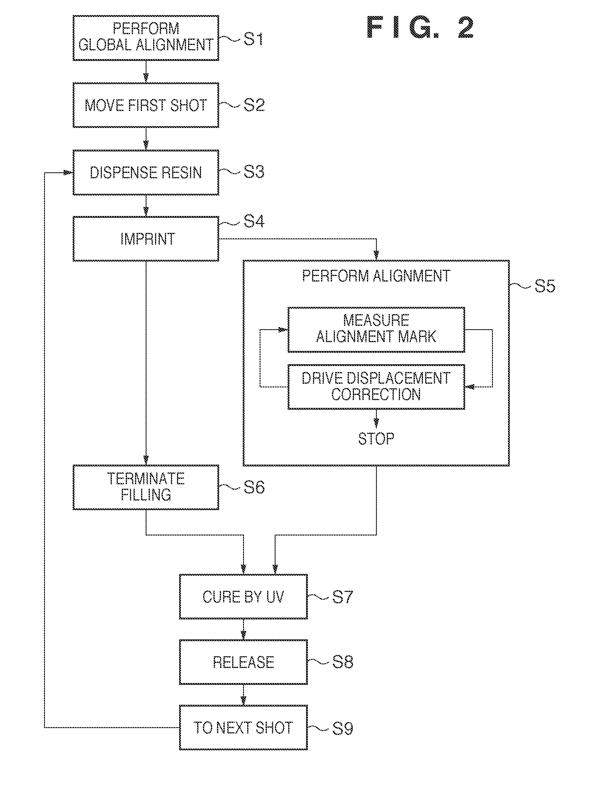
[0028]The procedure of the imprint process will be explained below with reference to FIG. 2. The imprint process will be described based on the global alignment method because while the template 3 comes in contact with a resin, there is no difference in alignment between the global alignment method and die-by-die method. In S1, the imprint apparatus performs global alignment by using the off-axis scope 9. In S2, the imprint apparatus drives the wafer stage 1 to move the first shot position of the wafer 2 to a dispensing start position below the dispenser 7. In S3, the imprint apparatus dispenses a resin on the first shot while scanning the wafer stage 1. In S4, the imprint apparatus drives the wafer stage 1 to move the first shot to a position immediately below the template 3, and starts an imprint step. In this imprint step, nozzles 20 discharge helium (He) to fill the space between the template 3 and wafer 2 with He, in order to purge oxygen.
[0029]A process in which the resin is f...
second embodiment
[0036]In the second embodiment, a scope 5 for use in the step (S5) of measuring an alignment mark 103 differs from that of the first embodiment. FIG. 9 is an enlarged view of the scope 5 of the second embodiment, which measures the alignment mark 103 by oblique illumination. One merit of the oblique illumination scope 5 is to avoid the interference with an illumination system 6. Marks 107 and 108 forming a wafer mark 120 on a wafer 2 and the template mark 103 are close to each other with a resin 200 being sandwiched between them. Light emitted from a light source 12 and coaxially synthesized by a synthetic prism 10 illuminates the marks 107 and 108. The marks 107 and 108 and the template mark 103 form lattice marks having different pitches so as to generate moire signals by the relative positions of these marks. In this arrangement, light diffracted by the marks 107 and 108 by oblique illumination must return to the optical axis of the scope 5. As shown in FIG. 8, therefore, a pitch...
third embodiment
[0037]In the first and second embodiments, the displacement or deformation of the template 3 is measured from the displacement between the wafer mark 120 and template mark 103, and the measured displacement or deformation is corrected. However, the first and second embodiments have the problems that, for example, the wafer mark 120 is always necessary in addition to the stage reference mark 8, and the process flexibility of moire alignment is lower than that of off-axis alignment. To solve these problems, there is a method of measuring the displacement of the template mark 103 by referring to a reference mark formed in the scope 5, instead of the wafer mark 120.
[0038]As shown in FIG. 10, in a position optically conjugate with a template mark 103, a slit 13 as a reference mark is inserted between a light source 12 and template 3. The slit 13 is a diffractive slit having two different pitches P1′ and P2′. Measurement light emitted from the light source 12 and passed through the slit 1...
PUM
| Property | Measurement | Unit |
|---|---|---|
| time | aaaaa | aaaaa |
| width | aaaaa | aaaaa |
| depth | aaaaa | aaaaa |
Abstract
Description
Claims
Application Information
 - R&D
- Intellectual Property
- Life Sciences
- Materials
- Tech Scout
- Unparalleled Data Quality
- Higher Quality Content
- 60% Fewer Hallucinations
Browse by: Latest US Patents, China's latest patents, Technical Efficacy Thesaurus, Application Domain, Technology Topic, Popular Technical Reports.
© 2025 PatSnap. All rights reserved.Legal|Privacy policy|Modern Slavery Act Transparency Statement|Sitemap|About US| Contact US: help@patsnap.com