Muscle biopsy clamp

a muscle biopsy and clamping technology, applied in the field of muscle biopsy clamps, can solve the problems of time-consuming, difficult, and expensive diffraction with lasers, and achieve the effects of enhancing tissue grasping/securement, minimizing tissue damage, and enhancing tissue securemen

Inactive Publication Date: 2011-08-25
RGT UNIV OF CALIFORNIA +1
View PDF2 Cites 9 Cited by
  • Summary
  • Abstract
  • Description
  • Claims
  • Application Information

AI Technical Summary

Benefits of technology

A representative embodiment of this aspect of the invention is the clamp (10) shown in FIG. 1. The clamp shown has two securing arms (12) movably connected about a pivot, a jaw arm 14 attached to each securing arm (12) such that the distal end of the jaw arm defines a jaw (16). As those in the art will appreciate, such clamps can be opened and closed in order to secure a tissue sample, for example, bundles of muscle fiber in vivo, between the jaw extensions (shown in exemplary fashion as elements 16a and 16b in FIG. 5). In some preferred embodiments, the opposing surfaces of the jaw extensions (i.e., the tissue-contacting surfaces) can include structures, such as serrations, lands and grooves, etc. that allow for enhanced tissue securement, as compared to flat, smooth surfaces. The invention also includes embodiments wherein the opposing surfaces of the jaw extensions are coated with plastic, rubber, or other natural or synthetic material to enhance tissue grasping / securement and / or minimize damage to tissue clamped or secured between the jaws, particularly the jaw extensions.

Problems solved by technology

However, in vivo laser diffraction can be a difficult, time consuming, and expensive endeavor that has only been performed in selected muscles.

Method used


Image

  • Muscle biopsy clamp
  • Muscle biopsy clamp
  • Muscle biopsy clamp

Examples


example i

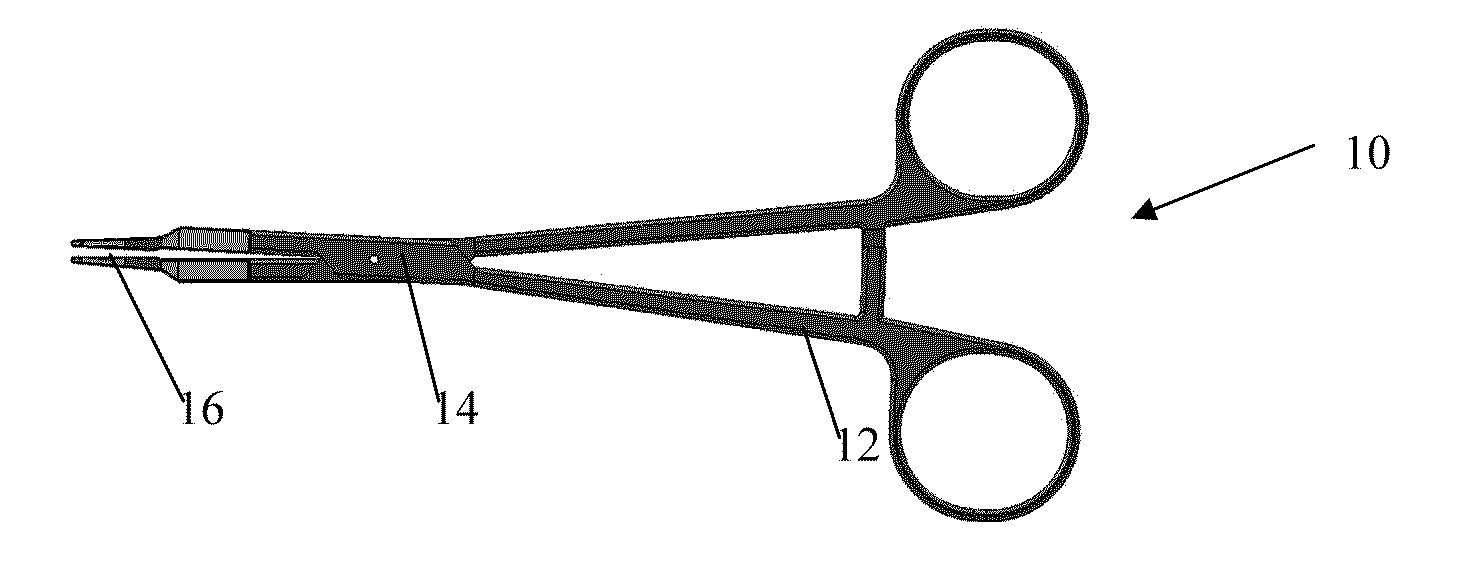
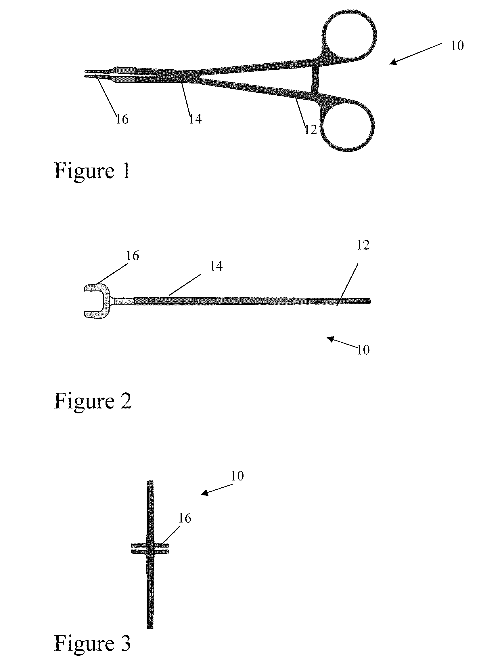
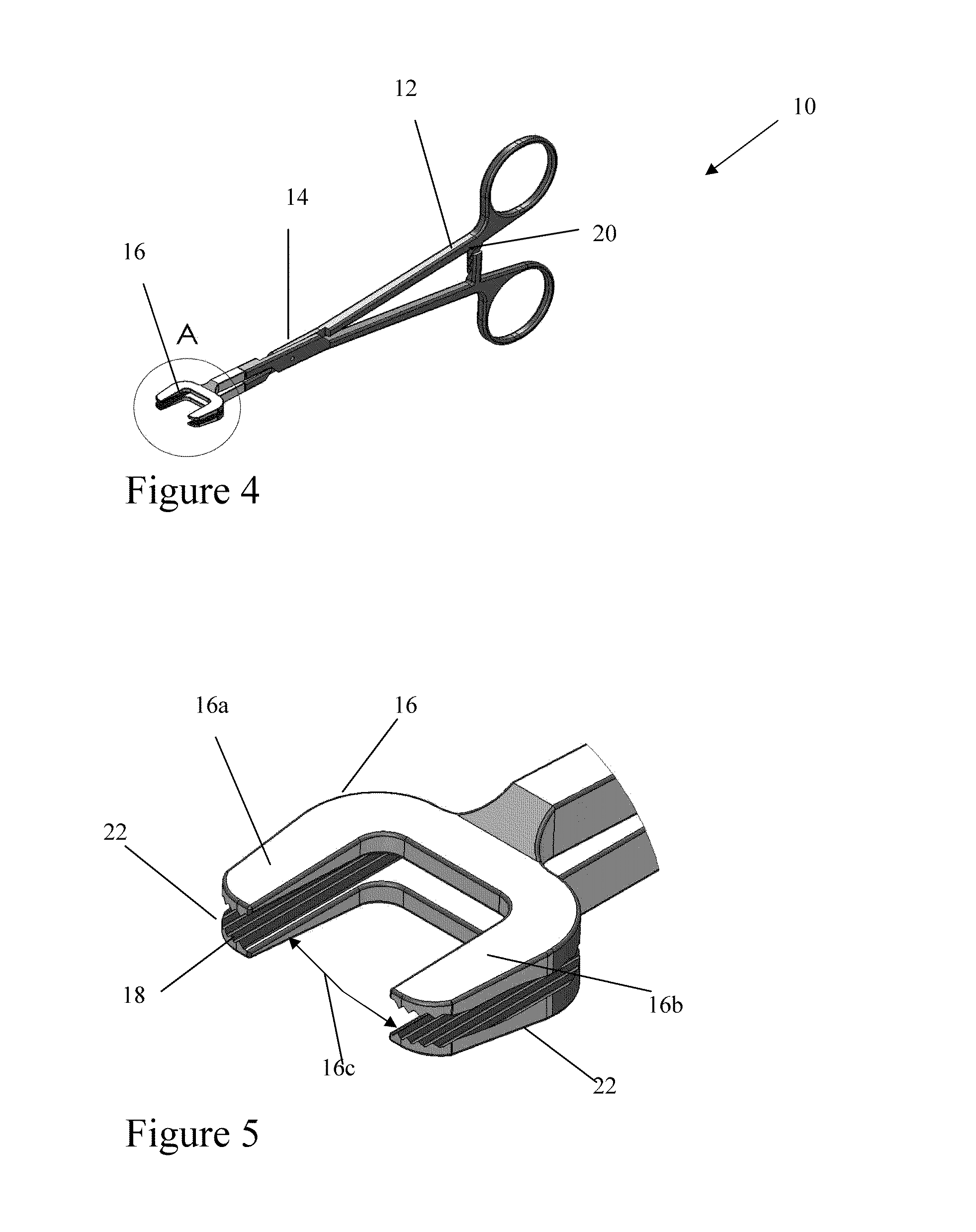
Fourteen centimeter long stainless steel hemostat clamps (Model 3-113-14, Sabri Group, Pompano Beach, Fla., USA) were modified by attaching custom 1 cm wide serrated jaws to their ends (See FIGS. 1 through 6). The jaws were machined from stainless steel (316) blocks using wire electrical discharge machining (EDM) to achieve very tight tolerances (±0.0005 cm) between mating jaw serrations (See FIGS. 5 and 6). After the jaws were machined, they were welded to the hemostat jaws using tungsten inert gas (TIG) and polished. This machining process allowed the jaws to be sterilized using standard autoclaving and provided sufficient clamping pressure to prevent slippage of muscle fibers between the jaws.

To validate sarcomere lengths obtained using the clamp-based method, biopsies (n=23) of the tibialis anterior muscles of New Zealand White rabbits (n=19) were sampled. Animals were induced and maintained under gas anesthesia (isoflurane 2%) in accordance with the Veterans Administration Inst...


PUM


Abstract

A muscle biopsy clamp device may be used to measure sarcomere lengths in vivo where laser diffraction may not be possible. The clamp device includes a jaw having serrated markings for securing a muscle bundle in the clamp device as well as to provide markings for the muscle biopsy as reference for the sarcomere length measurement.

Description

BACKGROUND OF THE INVENTIONMuscle architecture measurements provide quantitative estimates of muscle performance (Williams and Goldspink, 1978; Bodine et al., 1982; Powell et al., 1984). These values are critical input parameters for biomechanical modeling of the musculoskeletal system. However, architectural values only provide an estimate of the maximum force generating potential (Powell et al., 1984), maximum shortening velocity (Bodine et al., 1982), or maximum excursion (Williams and Goldspink, 1978) of a muscle. Muscle physiological properties, specifically the length-tension and force-velocity relations, provide a more functional understanding of muscle performance. In fact, these characteristics can modulate muscle force by 100%. Therefore, accurate estimates of a muscle's in vivo functional properties are required.To characterize muscle sarcomere length-tension properties, investigators have traditionally relied on microscopy to estimate in vitro sarcomere length on a very ...

Claims


Application Information

Patent Timeline
Patent Type & Authority Applications(United States)
IPC IPC(8): A61B17/28
CPCA61B10/06A61B2017/2808A61B2017/00858A61B17/282
Inventor WARD, SAMUEL R.LIEBER, RICHARD L.
Owner RGT UNIV OF CALIFORNIA
Why Eureka
Try Eureka