Total disc replacement with w-shaped spring elements

a technology of w-shaped springs and total discs, applied in the field of total disc replacement with w-shaped spring elements, can solve the problem that typical motion preservation devices do not replicate anatomical motions

Active Publication Date: 2011-08-25
SYNTHES USA
View PDF63 Cites 6 Cited by
  • Summary
  • Abstract
  • Description
  • Claims
  • Application Information

AI Technical Summary

Problems solved by technology

Typical motion preservation devices do not replicate the anatomical motions and reactions of an intervertebral disc.
Specifically, certain implants restrict most motions at the impacted level to a limited amount of pivoting or pitching between the vertebrae.

Method used


Image

  • Total disc replacement with w-shaped spring elements
  • Total disc replacement with w-shaped spring elements
  • Total disc replacement with w-shaped spring elements

Examples


Embodiment Construction

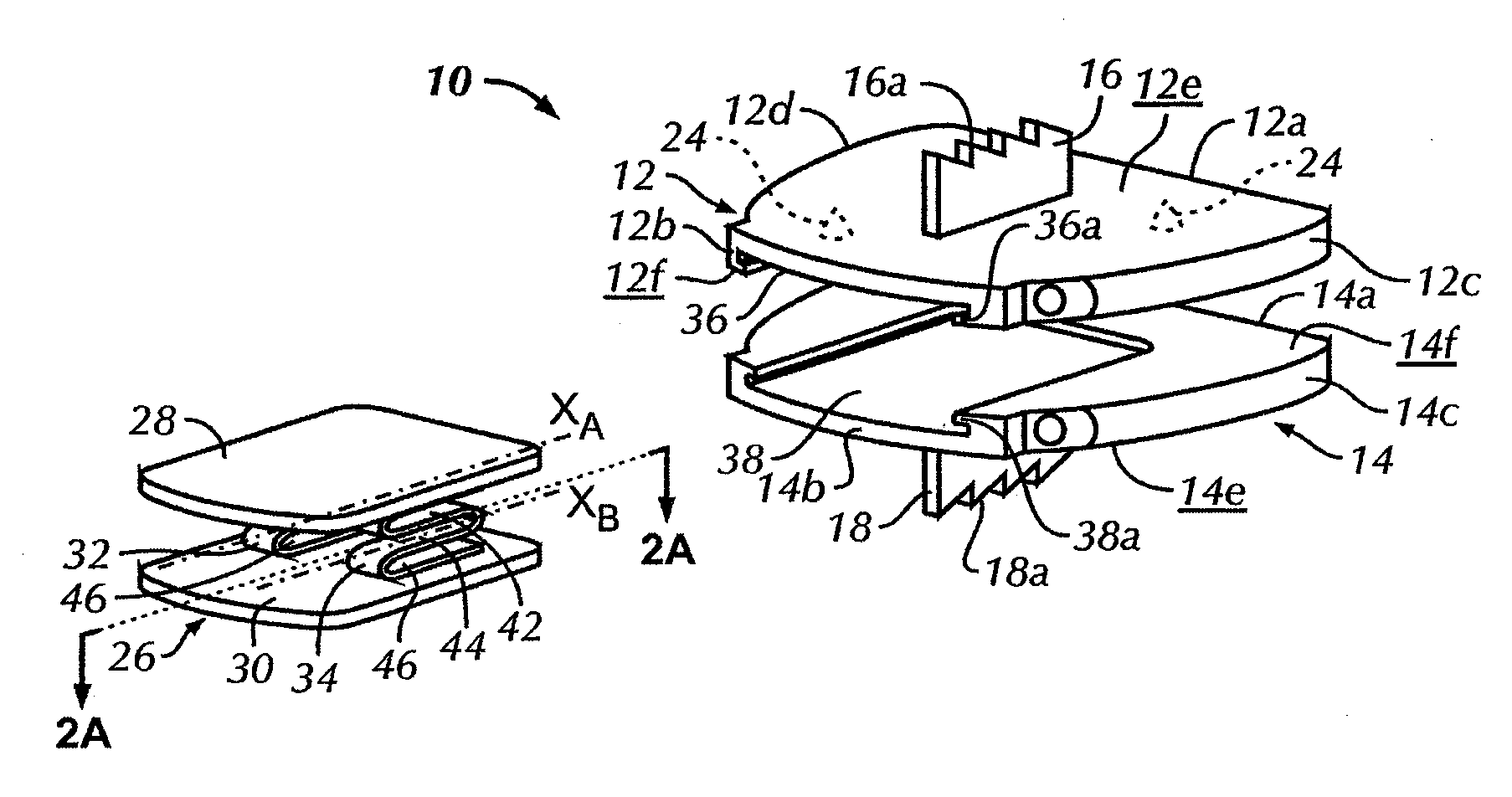
[0015]Certain terminology is used in the following description for convenience only and is not limiting. The words “right,”“left,”“lower,” and “upper” designate directions in the drawings to which reference is made. The words “inwardly” or “distally” and “outwardly” or “proximally” refer to directions toward and away from, respectively, the geometric center of the exemplary implants and instruments and related parts thereof. The words, “anterior,”“posterior,”“superior,”“inferior,”“lateral,”“medial,” and related words and / or phrases designate preferred positions and orientations in the human body to which reference is made and are not meant to be limiting. The terminology includes the above-listed words, derivatives thereof and words of similar import.

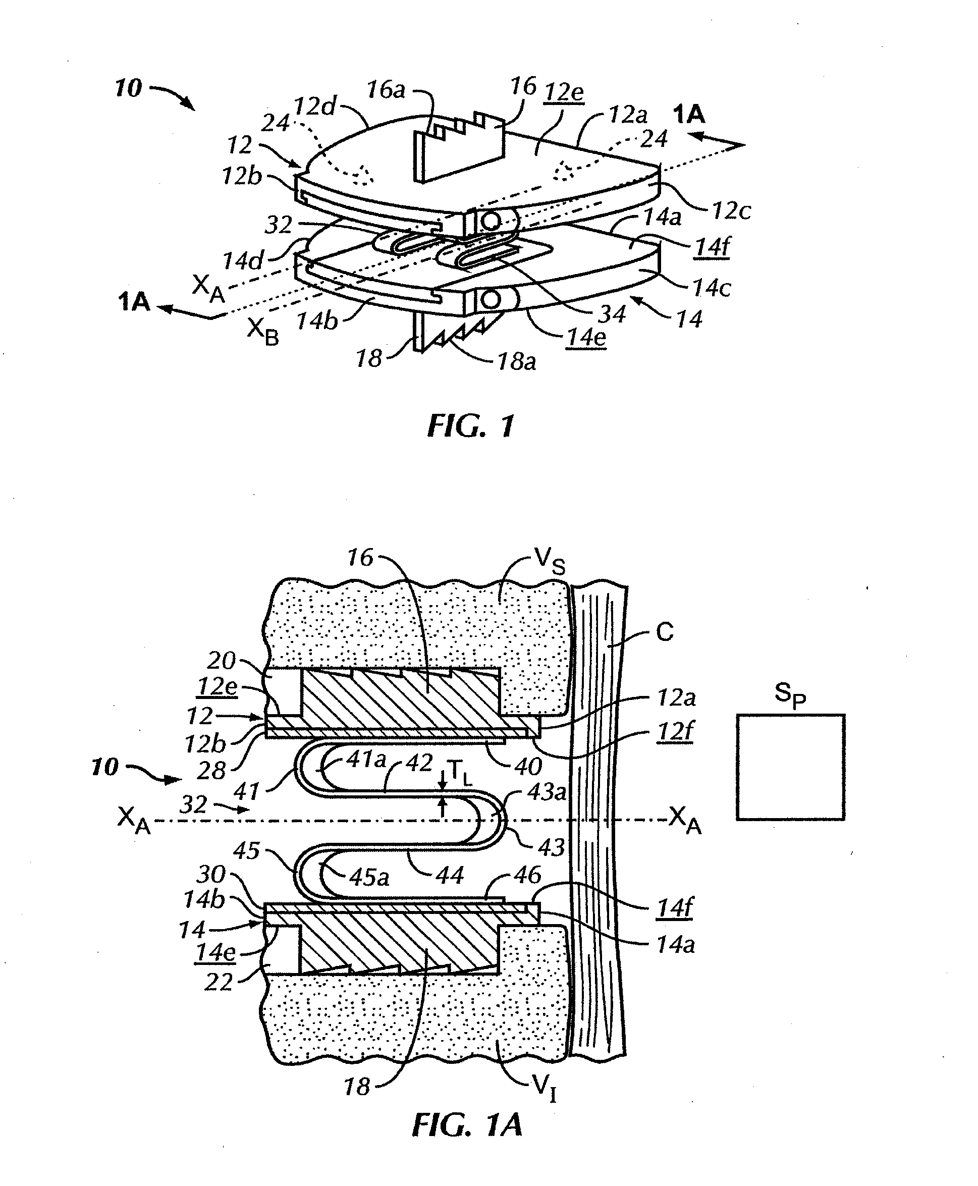
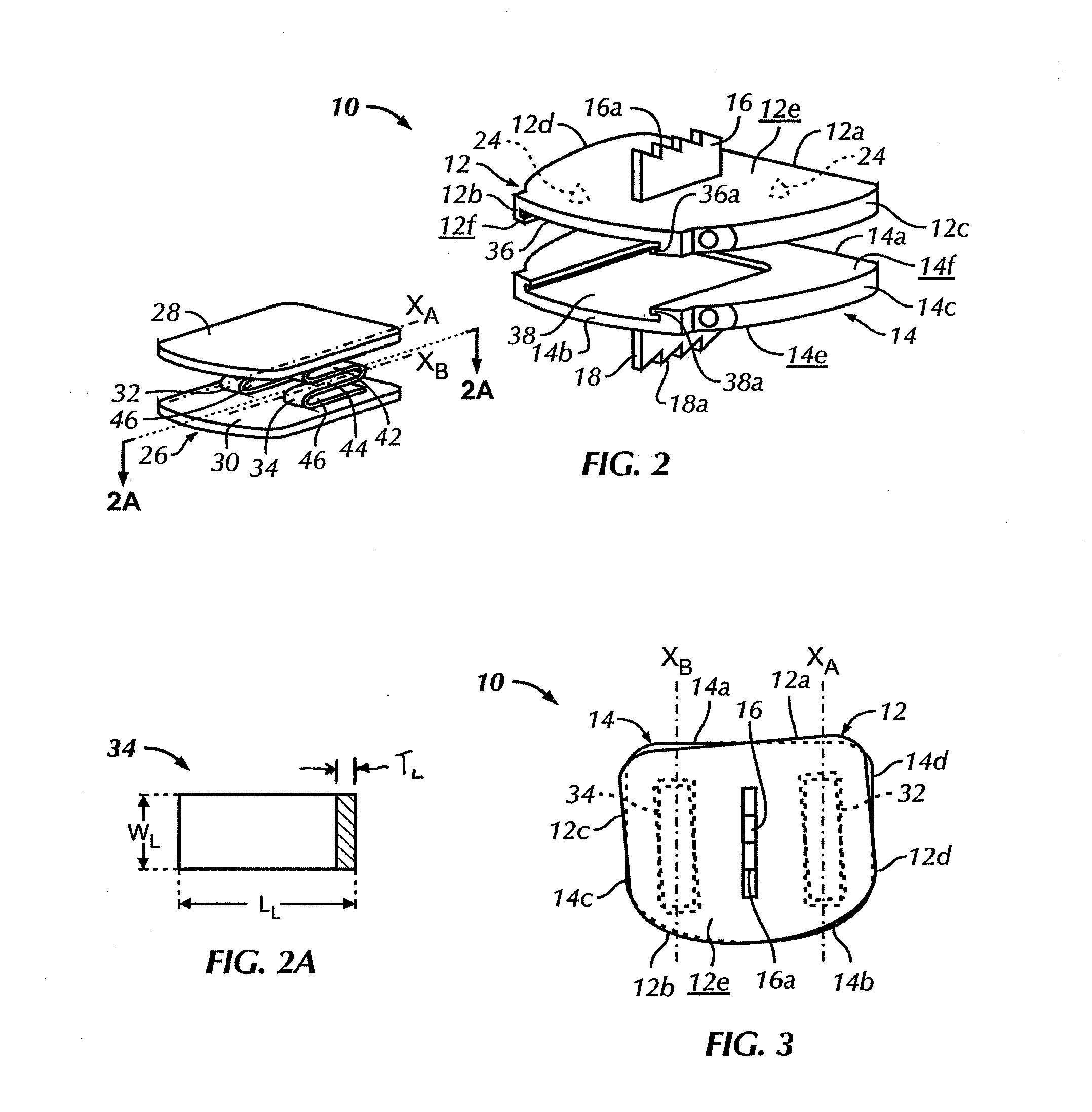
[0016]Referring to FIGS. 1-3, in a first exemplary embodiment, an intervertebral implant 10 for mounting between a superior vertebra VS and an inferior vertebra VI is comprised of a total disc replacement implant 10 that permits motion ...


PUM


Abstract

An intervertebral implant for mounting between superior and inferior vertebrae includes first and second endplates and an inlay. The first endplate has a first vertebra engagement surface and a first inner surface. The first vertebra engagement surface is mounted to the superior vertebra in an implant positions. The second endplate has a second vertebra engagement surface and a second inner surface. The second vertebra engagement surface is mounted to the inferior vertebra in the implanted position. The inlay is mounted to and between the first and second inner surfaces in an assembled configuration. The inlay includes a first mounting plate, a second mounting plate, a first W-shaped spring and a second W-shaped spring. The first and second W-shaped springs are mounted between the first and second mounting plates. The first and second W-shaped springs have longitudinal axes that are generally parallel to the insertion axis.

Description

BACKGROUND[0001]Motion preservation intervertebral implants for use in spinal surgery are utilized to preserve motion at the motion segment that is impacted by the surgery. Typical motion preservation devices do not replicate the anatomical motions and reactions of an intervertebral disc. Specifically, certain implants restrict most motions at the impacted level to a limited amount of pivoting or pitching between the vertebrae. It is desirable to design and construct an intervertebral motion preservation implant that mimics physiological or anatomical motion of an intervertebral disc to repair a diseased or damaged disc to its original, anatomical dampening and motion limitations.BRIEF SUMMARY[0002]Briefly stated, one exemplary embodiment is directed to an intervertebral implant for mounting between a superior vertebra and an inferior vertebra including a first endplate, a second endplate and an inlay. The first endplate has a first leading end, a first trailing end, a first lateral...

Claims


Application Information

Patent Timeline
Patent Type & Authority Applications(United States)
IPC IPC(8): A61F2/44
CPCA61F2/30734A61F2250/0018A61F2002/30014A61F2002/30177A61F2002/30448A61F2002/30481A61F2002/30565A61F2002/30571A61F2002/30604A61F2002/30841A61F2002/30884A61F2002/30904A61F2002/448A61F2220/0025A61F2220/005A61F2230/0056A61F2/4425A61B17/70A61F2/28A61F2/44
Inventor LECHMANN, BEATZURSCHMIEDE, SILASVOISARD, CYRIL
Owner SYNTHES USA
Why Eureka
Try Eureka