System and method for waste heat recovery in exhaust gas recirculation

a waste heat recovery and waste gas technology, applied in liquid degasification, machine/engine, separation process, etc., can solve the problems of significant heat or thermal energy rejection by the heat exchanger, limited design and efficiency of existing egr systems for the operation of combustion sources, and overall reduced engine system efficiency

Inactive Publication Date: 2011-09-01
GENERAL ELECTRIC CO
View PDF7 Cites 127 Cited by
  • Summary
  • Abstract
  • Description
  • Claims
  • Application Information

AI Technical Summary

Problems solved by technology

Production of emissions from mobile and stationary combustion sources such as locomotives, vehicles, power plants, and the like, contribute to environmental pollution.
However, existing EGR systems are limited in their design and efficiency for operation of the combustion sources under various operating conditions.
Given the high rates of exhaust gas recirculation required to meet the emission regulations, the amount of heat or thermal energy rejected by the heat exchanger can be significant.
Accordingly, this rejection of thermal energy results in an overall decreased efficiency of the engine system.

Method used


Image

  • System and method for waste heat recovery in exhaust gas recirculation
  • System and method for waste heat recovery in exhaust gas recirculation
  • System and method for waste heat recovery in exhaust gas recirculation

Examples


Embodiment Construction

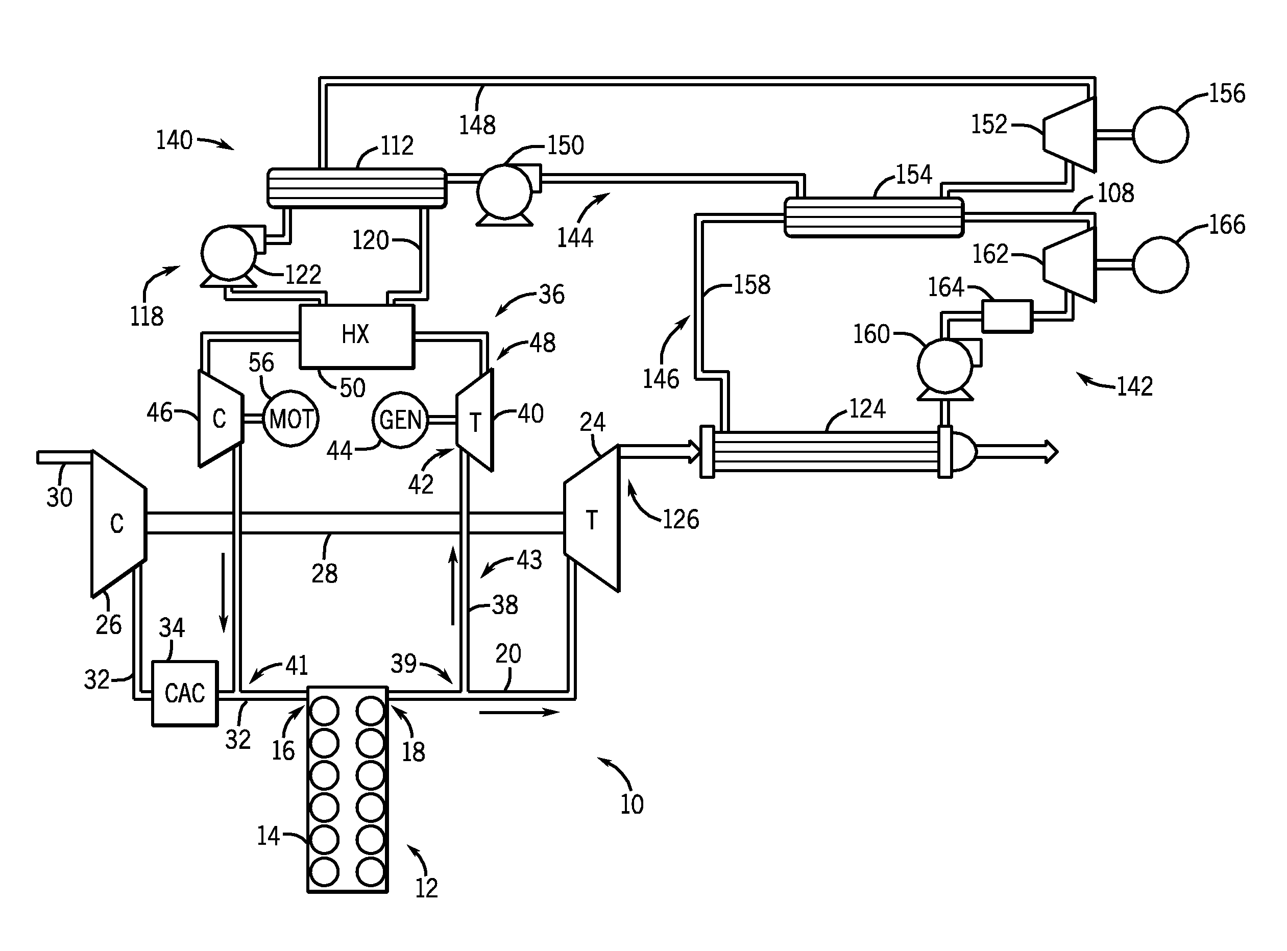
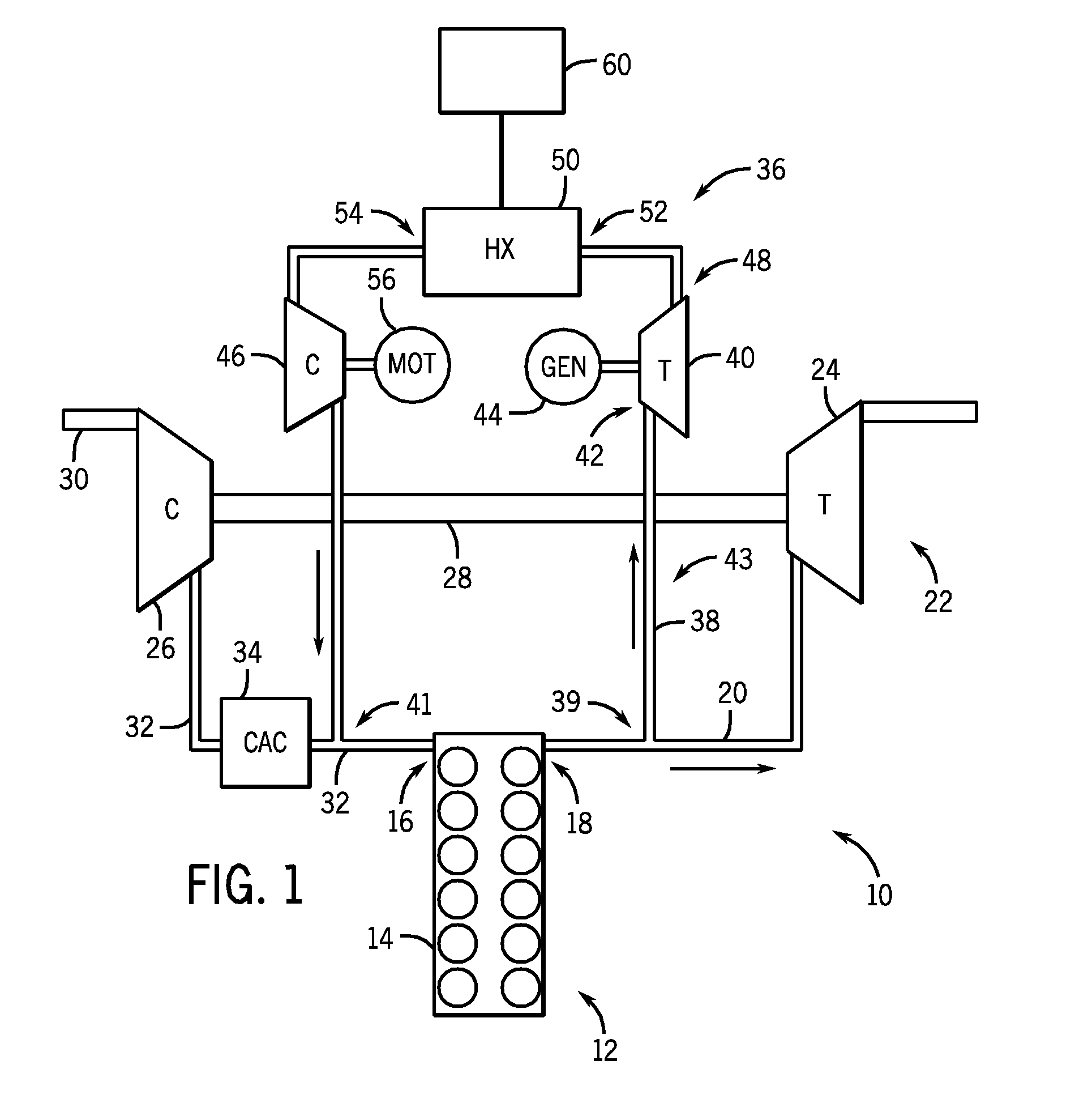
[0019]Referring to FIG. 1, a schematic illustration of an internal combustion engine system generally designated 10 is illustrated. The internal combustion engine system includes both mobile applications (e.g., automobiles, locomotives) and stationary applications (e.g., power plants). For ease in discussion, the internal combustion engine system 10 is discussed hereinafter in relation to a compression ignition engine system with the understanding that the discussion can readily be applied to other systems (e.g., systems that employ both spark ignition and compression ignition).

[0020]The internal combustion engine system 10 comprises an engine 12, which includes an engine body 14, an air intake manifold 16, and an exhaust manifold 18. The air intake manifold 16 serves to deliver intake air (e.g., an oxygen-containing gas) to combustion chambers (e.g., cylinders) in the engine body 14 via intake valves (not shown). That is, the intake manifold 16 is connected with the combustion cham...


PUM

PropertyMeasurementUnit
mechanical poweraaaaaaaaaa
temperatureaaaaaaaaaa
thermal energyaaaaaaaaaa

Abstract

A system and method for waste heat recovery in exhaust gas recirculation is disclosed. The system includes an engine having an intake manifold and an exhaust manifold, an exhaust conduit connected to the exhaust manifold, and a turbocharger having a turbine and a compressor, the turbine being connected to the exhaust conduit to receive a portion of the exhaust gas from the exhaust manifold. The system also includes an EGR system connected to the exhaust conduit to receive a portion of the exhaust gas, with the EGR system including an EGR conduit that is connected to the exhaust conduit to receive a portion of the exhaust gas, a heat exchanger connected to the EGR conduit and being configured to extract heat from the exhaust gas, and a waste heat recovery system connected to the heat exchanger and configured to capture the heat extracted by the heat exchanger.

Description

BACKGROUND OF THE INVENTION[0001]Embodiments of the invention relate generally to engine exhaust emission reduction systems and, more particularly, to a system and method for waste heat recovery in exhaust gas recirculation.[0002]Production of emissions from mobile and stationary combustion sources such as locomotives, vehicles, power plants, and the like, contribute to environmental pollution. One particular source of such emissions are nitric oxides (NOx), such as NO or NO2, emissions from vehicles, locomotives, generators, and the like. Environmental legislation restricts the amount of NOx that can be emitted by vehicles. In order to comply with this legislation, exhaust gas recirculation (EGR) systems have been implemented to reduce the amount of NOx emissions. However, existing EGR systems are limited in their design and efficiency for operation of the combustion sources under various operating conditions.[0003]Typically, EGR systems are arranged such that a desired quantity of...

Claims


Application Information

Patent Timeline
Patent Type & Authority Applications(United States)
IPC IPC(8): F02B33/44F01K23/10F01B31/10
CPCF01K23/065F01N5/02F02B37/007F02M25/0713F02M25/0735Y02T10/166F02M25/074Y02T10/121Y02T10/144Y02T10/16F02M25/0739F02M26/10F02M26/30F02M26/34F02M26/35Y02T10/12
Inventor FRITZ, JASSINBIKAS, GEORGIOSAST, GABORSIMPSON, ALEXANDERFREY, THOMAS JOHANNESERDMENGER, RODRIGO RODRIGUEZ
Owner GENERAL ELECTRIC CO
Why Eureka
Try Eureka