Method and equipment for providing the edge of a starting sheet with a dielectric strip

a dielectric strip and starting sheet technology, applied in the direction of cocoa, sweetmeats, dough shaping, etc., can solve the problems of poor adhesion of the plastic strip to the edge portion of the plate-like component, and the production of metal is difficult to separate from the starting sheet, so as to achieve better penetration

Active Publication Date: 2011-09-01
METSO OUTOTEC (FINLAND) OY
View PDF5 Cites 6 Cited by
  • Summary
  • Abstract
  • Description
  • Claims
  • Application Information

AI Technical Summary

Benefits of technology

[0018]An advantage, which is achieved by the solution according to the invention, is that no gap is formed between the dielectric strip and the edge of the starting sheet of the electrode when the molten dielectric material shrinks, while the molten dielectric material solidifies in the die space to form the dielectric strip, adhering to the edge of the starting sheet of the electrode. For this reason, the strip remains firmly attached to the edge of the starting sheet of the electrode. This is of advantage particularly in the electrolytic refining or recovery process of metals. If there is no gap between the strip and the edge of the electrode's starting sheet, no electrolytic liquid is allowed between the strip and the edge of the electrode's starting sheet to weaken the seam between the edge of the electrode's starting sheet and the strip.
[0019]The solution according to the invention also provides the advantage that if that edge of the starting sheet of the electrode, which is at least in part fitted in the die space, is provided with openings that extend through the edge of the starting sheet of the electrode, pressing of the dielectric material also results in a better penetration of the dielectric material into the said through-openings of the edge of the starting sheet of the electrode to provide connections between the dielectric material on the opposite sides of the edge of the starting sheet of the electrode.
[0020]The solution according to the invention also provides the advantage that, as the dielectric material is pressed to the edge of the starting sheet of the electrode during the solidification, a condition of bearing stress remains in the dielectric strip, tending to keep the dielectric strip attached to the edge of the starting sheet of the electrode.

Problems solved by technology

In that case, the deposits of the produced metal that are accumulated on the two sides of the starting sheet are, at three sides thereof, attached to each other over the narrow edges of the starting sheet and, therefore, the deposits of the produced metal are very difficult to separate from the starting sheet.
A problem with the solution disclosed in the specification WO / 2005 / 057682 is the poor adhesion of the plastic strip to the edge portion of the plate-like component as a result of the shrinkage of the plastic material.

Method used


Image

  • Method and equipment for providing the edge of a starting sheet with a dielectric strip
  • Method and equipment for providing the edge of a starting sheet with a dielectric strip
  • Method and equipment for providing the edge of a starting sheet with a dielectric strip

Examples


first embodiment

[0077]FIGS. 3-6 show the operation of the equipment according to the invention.

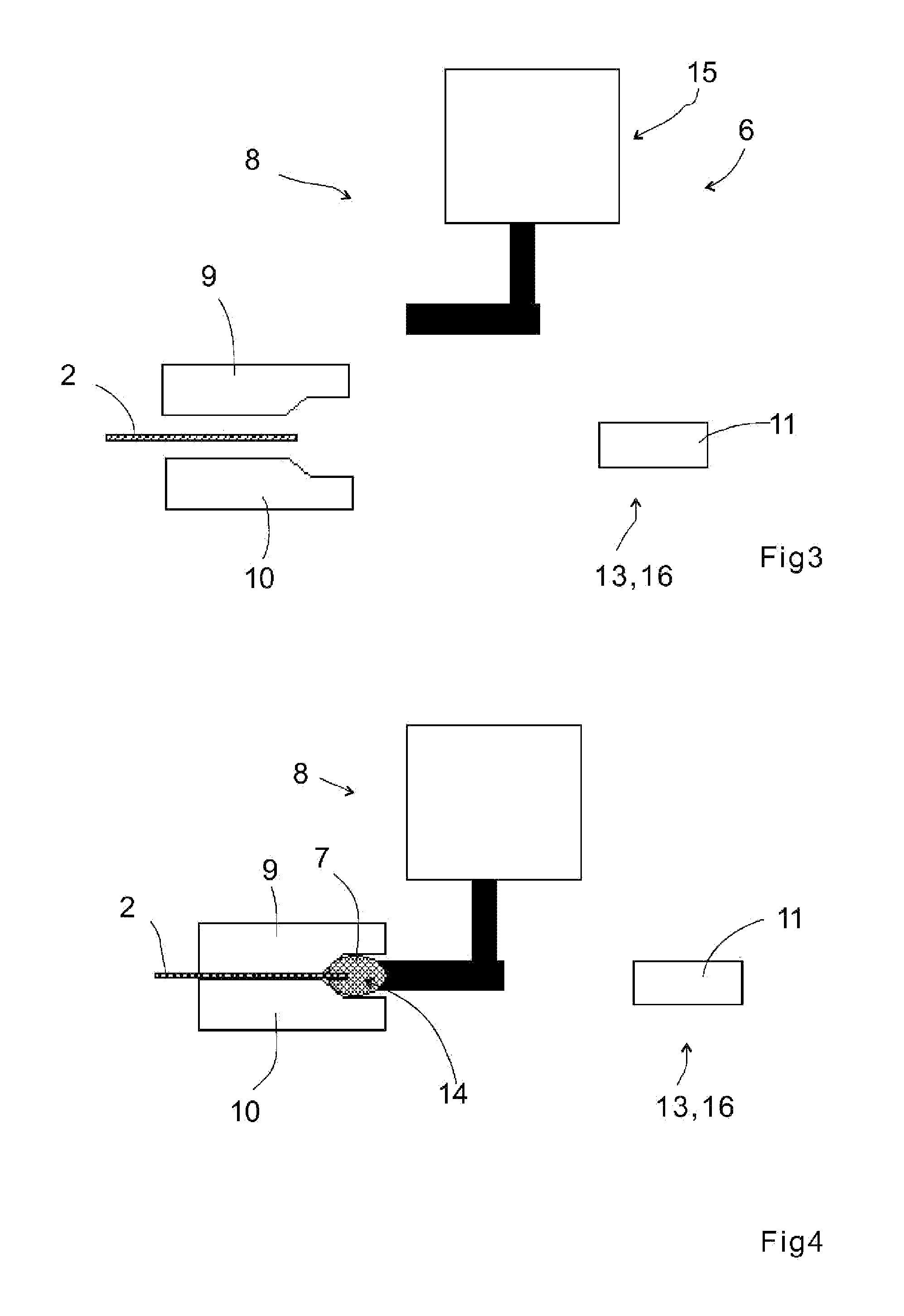
[0078]In FIG. 3, the edge 4 of the starting sheet 2 of the electrode is placed between two fixed 9 and moving die parts 10.

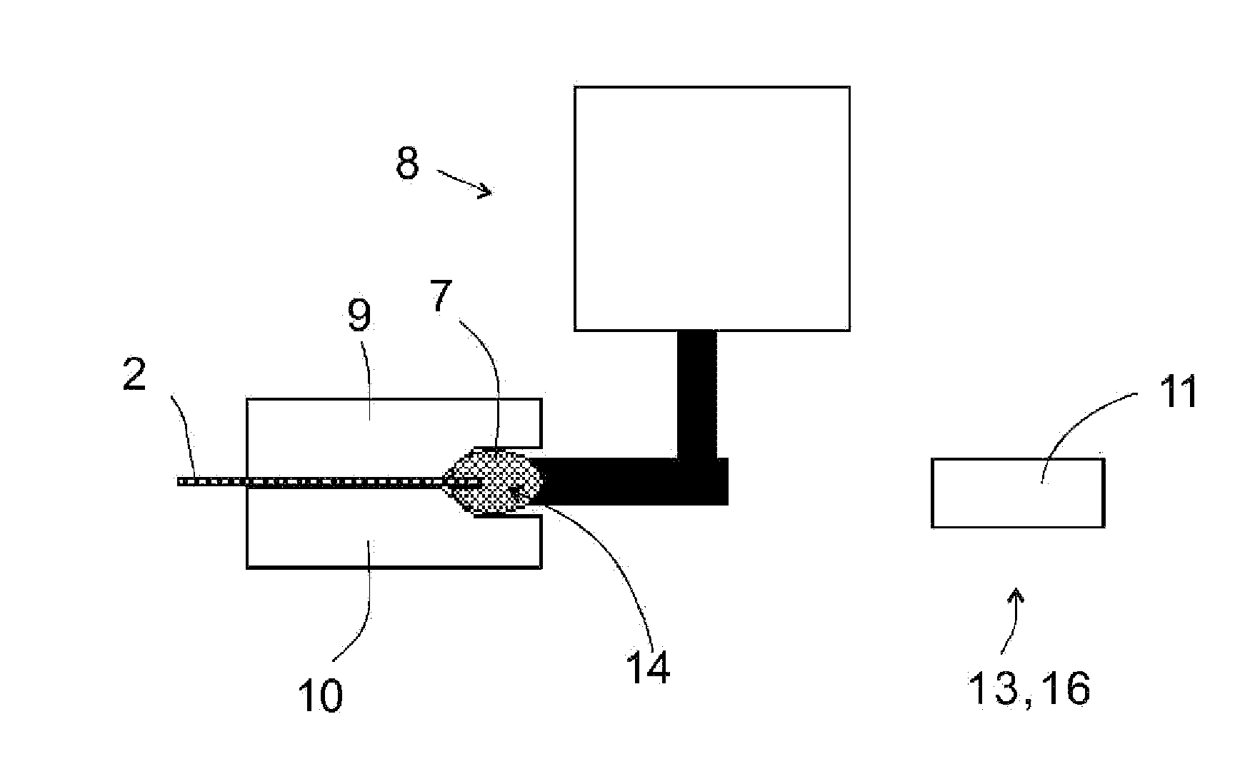
[0079]FIG. 4 shows a position after FIG. 3, wherein the die parts 9 and 10 are arranged with respect to the edge 4 of the starting sheet 2 of the electrode, so that a die space 7 is formed, wherein the edge 4 the starting sheet 2 of the electrode lies. In FIG. 4, the dielectric material 14; in this case, molten plastic material, is fed into the die space 7.

[0080]FIG. 5 shows a position after FIG. 4, wherein the changing member 13 of the volume of the die space 7 that is in the form of a pusher 11 presses the molten plastic material 14 in the die space 7, while the molten plastic material 14 in the die space solidifies, forming the strip 5 that consists of plastic material on the edge 4 of the starting sheet 2 of the electrode.

[0081]FIG. 6 shows a position after FIG. 5, wherein the die...

second embodiment

[0082]FIGS. 7-10 show the operation of the equipment according to the invention.

[0083]In FIG. 7, the edge 4 of the starting sheet 2 of the electrode is placed between two fixed die parts 9 and two moving die parts 10.

[0084]FIG. 8 shows a position after FIG. 7, wherein the fixed die part 9 and the moving die part 10 are arranged with respect to the edge 4 of the starting sheet 2 of the electrode, so that a die space 7 is formed, wherein the edge 4 of the starting sheet 2 of the electrode lies. In FIG. 4, the dielectric material 14; in this case, molten plastic material, is fed into the die space 7.

[0085]FIG. 9 shows a position after FIG. 4, wherein that changing member 13 of the volume of the die space 7, which is in the form of the moving die part 10 and which forms the pusher 11, presses the molten plastic material 14 in the die space 7, while the molten plastic material 14 solidifies in the die space and forms the strip 5, which consists of plastic material, on the edge 4 of the s...


PUM

PropertyMeasurementUnit
dielectricaaaaaaaaaa
volumeaaaaaaaaaa
adhesionaaaaaaaaaa

Abstract

A device for providing the edge of a starting sheet of an electrode used in the electrolytic refining or recovery of metals with a dielectric part comprises a die space, in which the edge of the starting sheet of the electrode can at least partly be fitted, and a feeding device of the dielectric material for feeding the dielectric material into the die space. The device comprises changing members of the volume of the die space for pressing the dielectric material in the die space to that edge of the starting sheet of the electrode, which is at least partly fitted in the die space.

Description

BACKGROUND OF THE INVENTION[0001]The invention relates to a method according to the preamble of claim 1 for providing the edge of the starting sheet of an electrode used in the electrolytic refining or recovery of metals with a dielectric strip.[0002]The invention relates to equipment according to the preamble of claim 16 for providing the edge of the starting sheet of an electrode used in the electrolytic refining or recovery of metals with a dielectric strip.[0003]In the electrolytic refining and recovery process, which is used as a sub-process in the manufacture of metals, such as copper, nickel and zinc, a starting sheet made of, for example, stainless steel, aluminium or titanium is used as the electrode, and the metal to be refined is precipitated on the different sides of the sheet by means of an electric current. The metal that is accumulated on the surface is detached from the starting sheet at regular intervals. Generally, the electrolytic refining and recovery process is ...

Claims


Application Information

Patent Timeline
Patent Type & Authority Applications(United States)
IPC IPC(8): B29C45/14
CPCB29C45/14336C25C7/02B29C70/763B29C45/14B29C70/76B29C45/0416B29C48/155
Inventor NORDLUND, LAURIHUOTARI, ARTO
Owner METSO OUTOTEC (FINLAND) OY
Why Eureka
Try Eureka