Thrust Balancing Device For Cryogenic Fluid Machinery

a technology of balancing device and cryogenic fluid, which is applied in the direction of liquid fuel engine, electric generator control, container discharging method, etc., can solve the problems of reducing affecting the operation efficiency of the machine, and affecting the reliability of the machine, so as to reduce the gap between the two.

Active Publication Date: 2011-09-01
ELLIOTT CO
View PDF12 Cites 12 Cited by
  • Summary
  • Abstract
  • Description
  • Claims
  • Application Information

AI Technical Summary

Benefits of technology

[0009]An object of this invention is to provide a way for the lower bearing to be disposed closer to the upper bearing, thereby reducing the gap therebetween, without interfering with the functioning of a thrust balancing mechanism.

Problems solved by technology

As the generator is the dominant component in terms of rotordynamic stability, the increased size has negative ramifications to the machine reliability.
For example, higher power ratings of variable speed hydraulic turbine generators implicitly require larger physical sizes, but the possible loss of generator load demands critical speed separation below continuous speed and above maximum “breakaway” speed.
Furthermore, in the design of cryogenic turbine generators and pumps, there limitations on bearing size, shaft diameter and overall diameter of machines of this type.
However this is not readily accomplished in machines having ball bearings which are cooled and lubricated by the product fluid.
The TEMs (Thrust Equalizing Mechanism) mechanisms incorporated in machinery designed by Ebara International Corporation, Sparks, Nev., are good examples of such thrust balancing mechanisms which employ a combination of fixed and variable orifices, but there are limitations with regards to location, length and resultant variable orifice gap size.

Method used


Image

  • Thrust Balancing Device For Cryogenic Fluid Machinery
  • Thrust Balancing Device For Cryogenic Fluid Machinery
  • Thrust Balancing Device For Cryogenic Fluid Machinery

Examples


Embodiment Construction

[0026]The description that follows is presented to enable one skilled in the art to make and use the present invention, and is provided in the context of a particular application and its requirements. Various modifications to the disclosed embodiments will be apparent to those skilled in the art, and the general principals discussed below may be applied to other embodiments and applications without departing from the scope and spirit of the invention. Therefore, the invention is not intended to be limited to the embodiments disclosed, but the invention is to be given the largest possible scope which is consistent with the principals and features described herein.

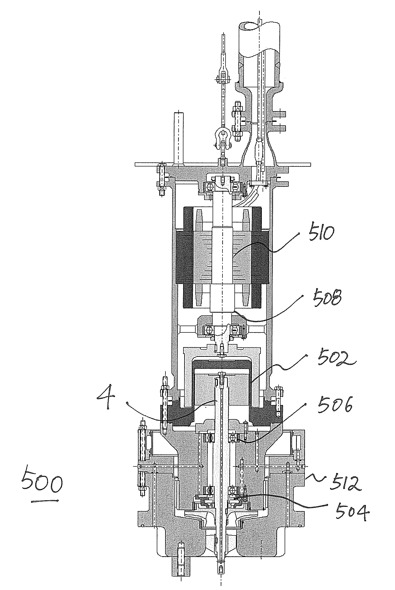
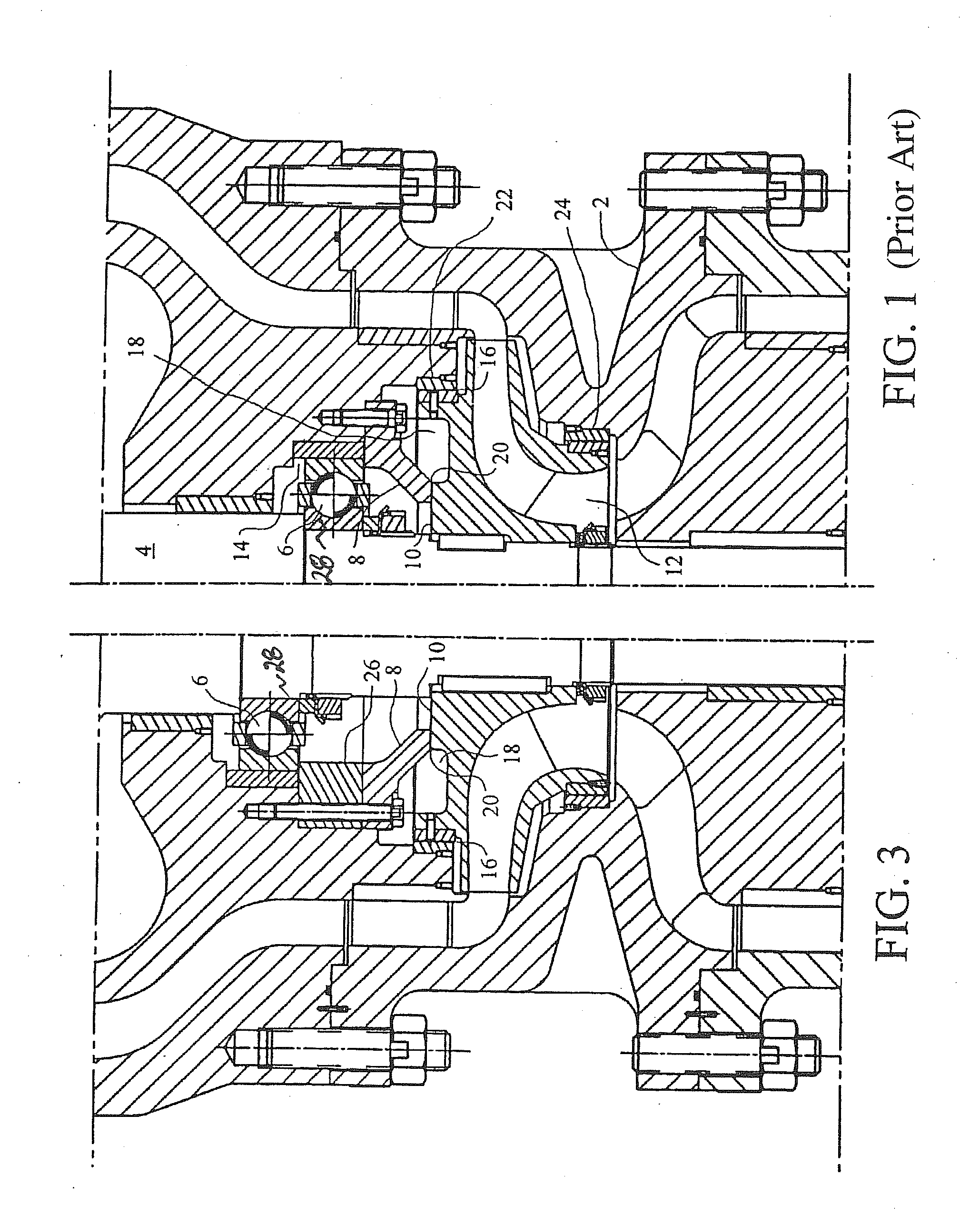
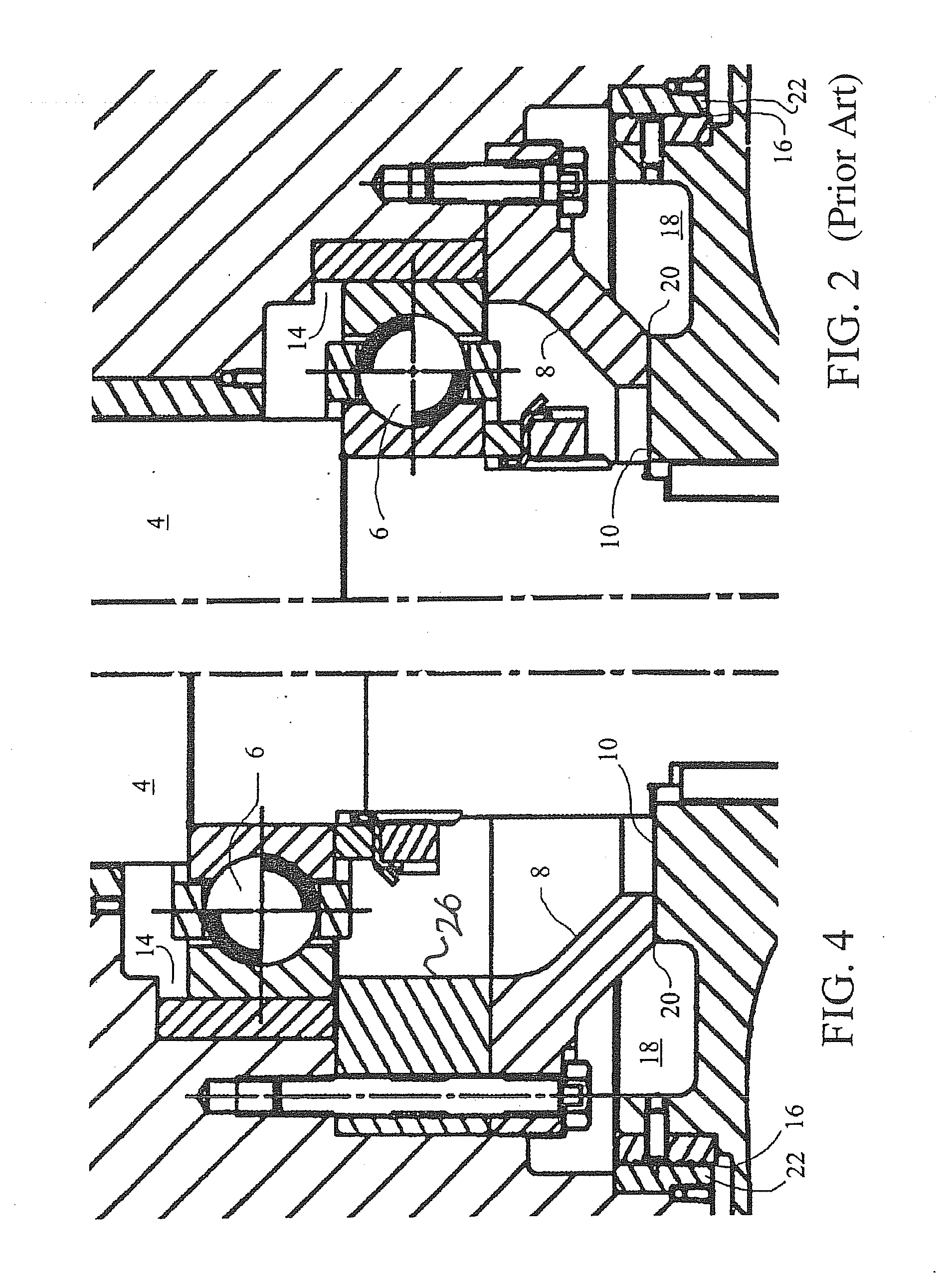
[0027]Referring to FIGS. 1 and 2, a prior art machine with a conventional thrust equalizing mechanism, hereafter “TEM”, is illustrated to have a housing 2, a shaft 4, a lower bearing 6, a stationary thrust plate 8, a throttle ring 10 affixed to the shaft 4, a runner 12, a gap 14 above the lower bearing which allows the shaft...


PUM


Abstract

An improvement for a turbine generator or pump having main bearings separated by a span of shaft and a thrust equalizing mechanism adjacent one of said main bearings, the improvement comprising a stationary length compensator interposed between the thrust equalizing mechanism and its adjacent main bearing to reduce the span between said main bearings. Preferably the length compensator is composed of material that shrinks less than the shaft of the generator, and the height of the length compensator, i.e., the compensating dimension, is selected according to desired thrust equalizing mechanism operating parameters over a temperature range.

Description

RELATED APPLICATIONS[0001]This application is a Continuation-In-Part application to U.S. patent application Ser. No. 10 / 776,555 filed Feb. 10, 2004, entitled “THRUST BALANCING DEVICE FOR CRYOGENIC FLUID MACHINERY”, Attorney Docket No. EIC-401, which is related to and a Non-Provisional application of U.S. Patent Application No. 60 / 446,460 filed Feb. 10, 2003, entitled “THRUST BALANCING DEVICE FOR CRYOGENIC FLUID MACHINERY”, Attorney Docket No. EIC-401-P, which are both incorporated herein by reference in their entirety, and claims any and all benefits to which they are entitled therefrom.FIELD OF THE INVENTION[0002]The present invention relates in general to means and methods for balancing the thrust felt by pumps and turbine generators operating in a cryogenic environment, and in particular to a novel improvement in a thrust balancing configuration to enhance the rotordynamic behavior of vertical cryogenic pumps and turbine generators.BACKGROUND OF THE INVENTION[0003]The Liquid Natu...

Claims


Application Information

Patent Timeline
Patent Type & Authority Applications(United States)
IPC IPC(8): H02K7/18F16C27/08F17C13/00
CPCF01D25/16F16C19/52F16C41/02F05D2240/52F05D2250/315F04D29/051F05D2300/50212H02K5/1672F04D29/041H02K7/1823F05D2230/642
Inventor MADISON, JOEL V.
Owner ELLIOTT CO
Why Eureka
Try Eureka