Novel Solar Power Circuits

a solar power circuit and solar energy technology, applied in the field of solar power circuits, can solve problems such as system vulnerability, and achieve the effect of reducing or eliminating the risk of circuit damage or related problems inherent in solar power circuits

Inactive Publication Date: 2011-09-01
AMPT
View PDF100 Cites 197 Cited by
  • Summary
  • Abstract
  • Description
  • Claims
  • Application Information

AI Technical Summary

Benefits of technology

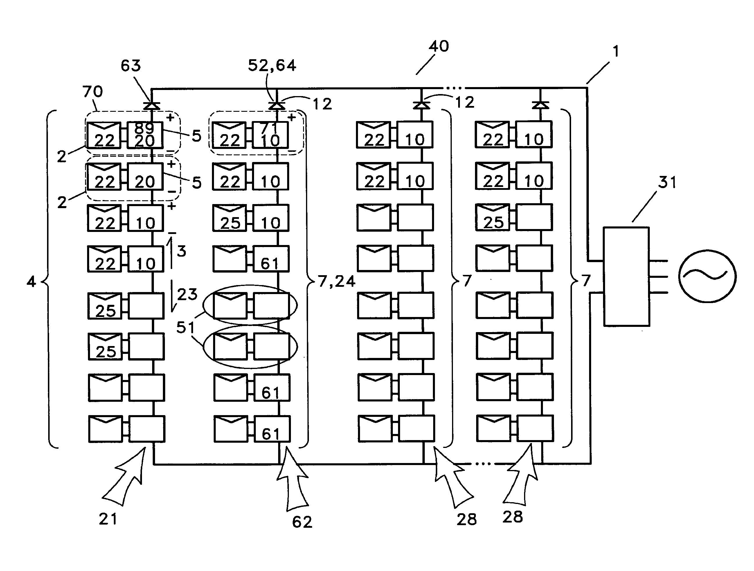
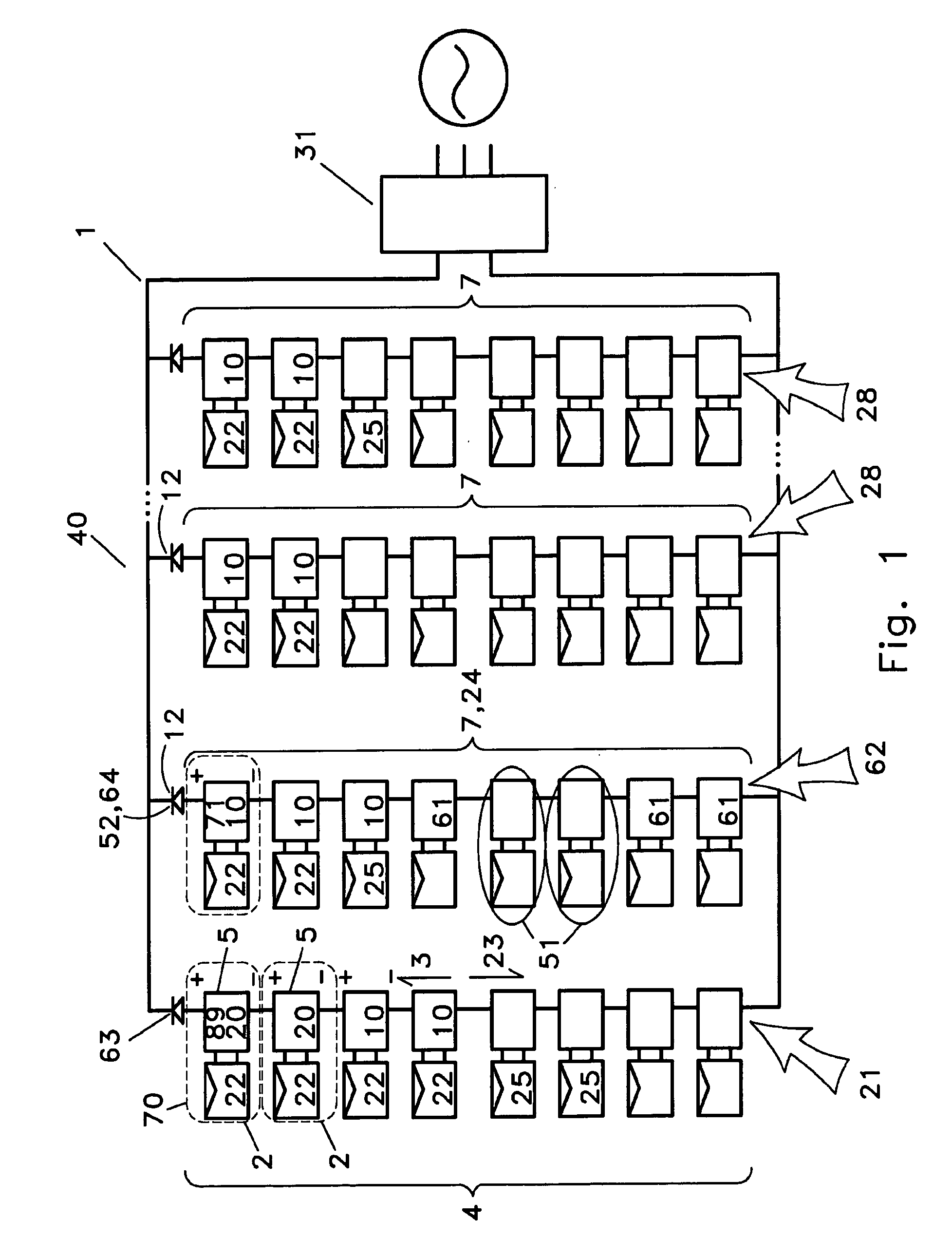
[0006]It is goal of at least one embodiment of the inventive technology to allow for voltage limitation of solar power supplies in a solar power circuit such as a solar array, and the benefits that result therefrom, while also reducing or eliminating the risk of circuit damage or related problems inherent therein.
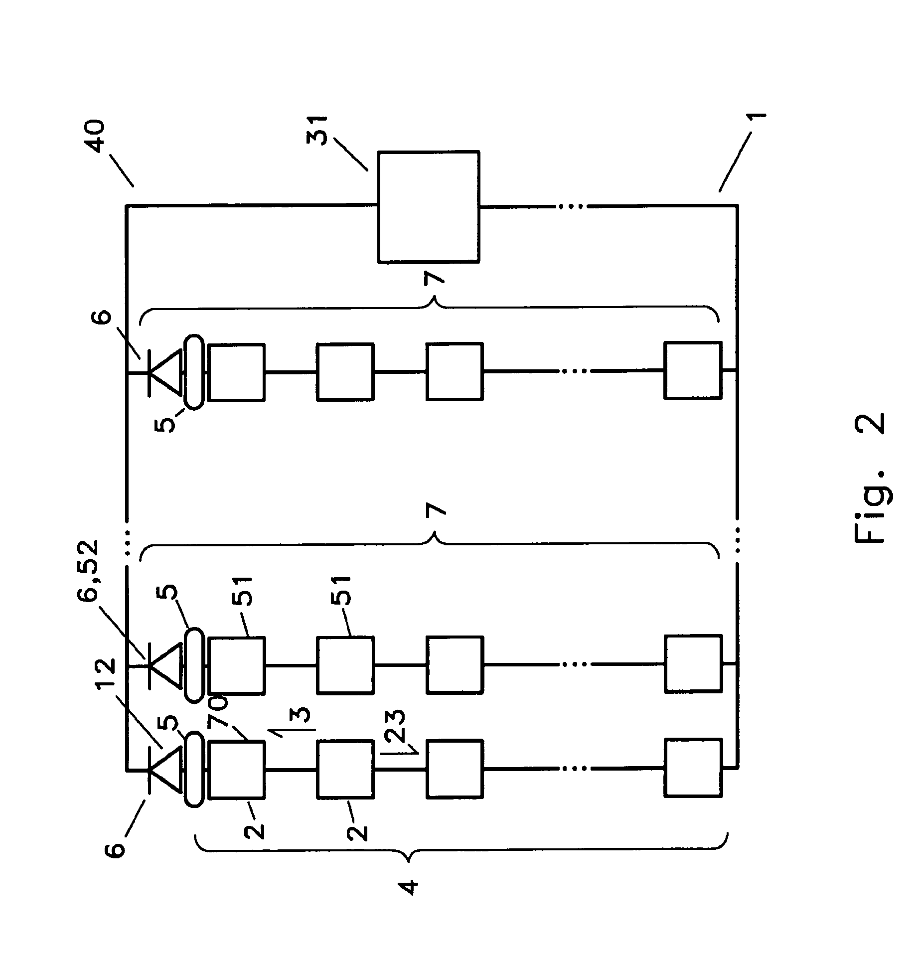
[0007]It is goal of at least one embodiment of the inventive technology to isolate ground faults / short circuits that may occur in a power supply array (e.g., a solar panel array) having serially connected converters, by preventing the flow of reverse current through the string having such fault or short circuit.

Problems solved by technology

Certain power conversion strategies, which, in solar power circuits, may include operation at MPP (maximum power point), and / or voltage limiting capability, may introduce system vulnerability.
One example of such vulnerability is found in the voltage limiting circuit of the converter disclosed in PCT / US2008 / 057105, where such vulnerability takes the form of reverse current sensitivity.

Method used


Image

  • Novel Solar Power Circuits
  • Novel Solar Power Circuits
  • Novel Solar Power Circuits

Examples


Embodiment Construction

[0019]As mentioned earlier, the present invention includes a variety of aspects, which may be combined in different ways. The following descriptions are provided to list elements and describe some of the embodiments of the present invention. These elements are listed with initial embodiments, however it should be understood that they may be combined in any manner and in any number to create additional embodiments. The variously described examples and preferred embodiments should not be construed to limit the present invention to only the explicitly described systems, techniques, and applications. Further, this description should be understood to support and encompass descriptions and claims of all the various embodiments, systems, techniques, methods, devices, and applications with any number of the disclosed elements, with each element alone, and also with any and all various permutations and combinations of all elements in this or any subsequent application.

[0020]In at least one e...


PUM


Abstract

Particular embodiments of the inventive technology disclosed herein seek to reduce or eliminate the risk of damage to components of photovoltaic power circuits such as solar arrays. Aspects of the inventive technology, in embodiments, utilize diode to prevent reverse current flow in the event of application of a voltage to a power supply string which would otherwise effect such flow. Prevention of such reverse current flow may preclude voltages that would otherwise damage reverse current sensitive devices such as switches that may form part of a voltage limiting DC to DC converter.

Description

TECHNICAL FIELD[0001]Generally, this inventive technology relates to power circuits. More specifically, aspects of this inventive technology relate to solar (photovoltaic) power circuits, and apparatus and methods that prevent or at least mitigate damage to power circuits that might otherwise occur during circuit operation.BACKGROUND ART[0002]Generation of power from alternative sources has received considerably more attention in recent past, due at least in part to the reduced desirability of what may be termed conventional sources such as coal and oil. Whether for cost, pollution, or other reasons, considerably more attention has been recently devoted to power generation from alternate sources such as solar. Although the inventive technology disclosed herein is not limited to electrical power circuits designed specifically as relate to power from alternate sources (e.g., solar), its conception was spurred by the need to improve solar powered circuits in particular.[0003]Generally,...

Claims


Application Information

Patent Timeline
Patent Type & Authority Applications(United States)
IPC IPC(8): H02J1/10
CPCH01L31/02021Y02E10/50H02J1/12H02J1/108
Inventor LEDENEV, ANATOLIPORTER, ROBERT M.
Owner AMPT
Why Eureka
Try Eureka