Integrated late lean injection on a combustion liner and late lean injection sleeve assembly

a technology of combustion liner and sleeve assembly, which is applied in the direction of turbine/propulsion fuel heating, machines/engines, lighting and heating apparatus, etc., can solve the problems of auto-ignition, safety hazards, and high cost of current late lean injection assemblies, so as to reduce/eliminate the risk of fuel leakage, easy to install into new units, and easy to retrofit

Inactive Publication Date: 2013-12-10
GENERAL ELECTRIC CO
View PDF90 Cites 12 Cited by
  • Summary
  • Abstract
  • Description
  • Claims
  • Application Information

AI Technical Summary

Benefits of technology

[0004]The present invention is directed to a late lean injection sleeve assembly, which combines the traditional liner and flow sleeve assemblies into an assembly with an internal fuel manifold and an air / fuel delivery system. The liner and flow sleeve assembly allows for reduced leakage and improved control of potential fuel leakage. The fuel required for late lean injection is supplied to the sleeve via a manifold ring in the flow sleeve flange. Single feed holes are drilled through the flow sleeve. The fuel is delivered through at least one passage in the flow sleeve into nozzles or injectors that mix the fuel with compressor discharge case (“CDC”) air before injecting it into the liner. Preferably, the at least one passage is one or more longitudinally extending holes or tubes in the flow sleeve, although a flow sleeve having co-annular walls could also be used to deliver the fuel to the nozzles or injectors. The number and size of nozzles / injectors can be varied, depending on the fuel supply requirement. The nozzles / injectors span both the flow sleeve and liner assemblies, providing a central core of late lean injection without air losses and potential fuel leakages.
[0006]The late lean injection sleeve assembly allows the injection of fuel at the aft end of a gas turbine liner, before the transition piece, into the combustion gases downstream of the fuel nozzles. The late lean injection enables fuel injection downstream of the fuel nozzles to create a combustion zone downstream before the turbine's transition piece, while reducing / eliminating the risk of fuel leaking into the combustor discharge case. The late lean injection sleeve assembly is easily retrofitted into existing turbine units and is easily installed into new units. It reduces the risk of fuel leaking into the CDC compartment by not having any non-welded interfaces.
[0007]The present invention is further directed to integrated late lean injection on a combustion liner, which provides a simple low cost option for late lean injection. This integrated late lean injection design is easily retrofitted on existing units and can be installed at a lower cost than current late lean injection designs. The design is a single assembly that is installed during unit assembly. The design has a forward flange that is used for both support and to feed the fuel to the injection tubes at the aft end of the liner. Fuel is supplied to an internal manifold in the forward flange and is then delivered to the injection tubes through the struts. The number and orientation of the struts can be varied depending on the amount of late lean injection that is required. The axial running tubes are supported along the length of the liner by struts that are welded to the liner body. This interface is designed to minimize wear between the tube struts and the tubes. Other means of transferring fuel from the manifold flange along the outside of the liner to the nozzles could also be used. This can be achieved by fittings into the flange manifold, as opposed to using struts.

Problems solved by technology

Multiple designs exist for staged combustion in gas turbines, but most are complicated assemblies consisting of a plurality of tubing and interfaces.
Current late lean injection assemblies are expensive and costly for both new gas turbine units and retrofits of existing units due to the number of parts and the complexity of the fuel passages.
Current late lean injection assemblies also have a high risk for fuel leakage into the compressor discharge casing, which can result in auto-ignition and be a safety hazard.

Method used


Image

  • Integrated late lean injection on a combustion liner and late lean injection sleeve assembly
  • Integrated late lean injection on a combustion liner and late lean injection sleeve assembly
  • Integrated late lean injection on a combustion liner and late lean injection sleeve assembly

Examples


Embodiment Construction

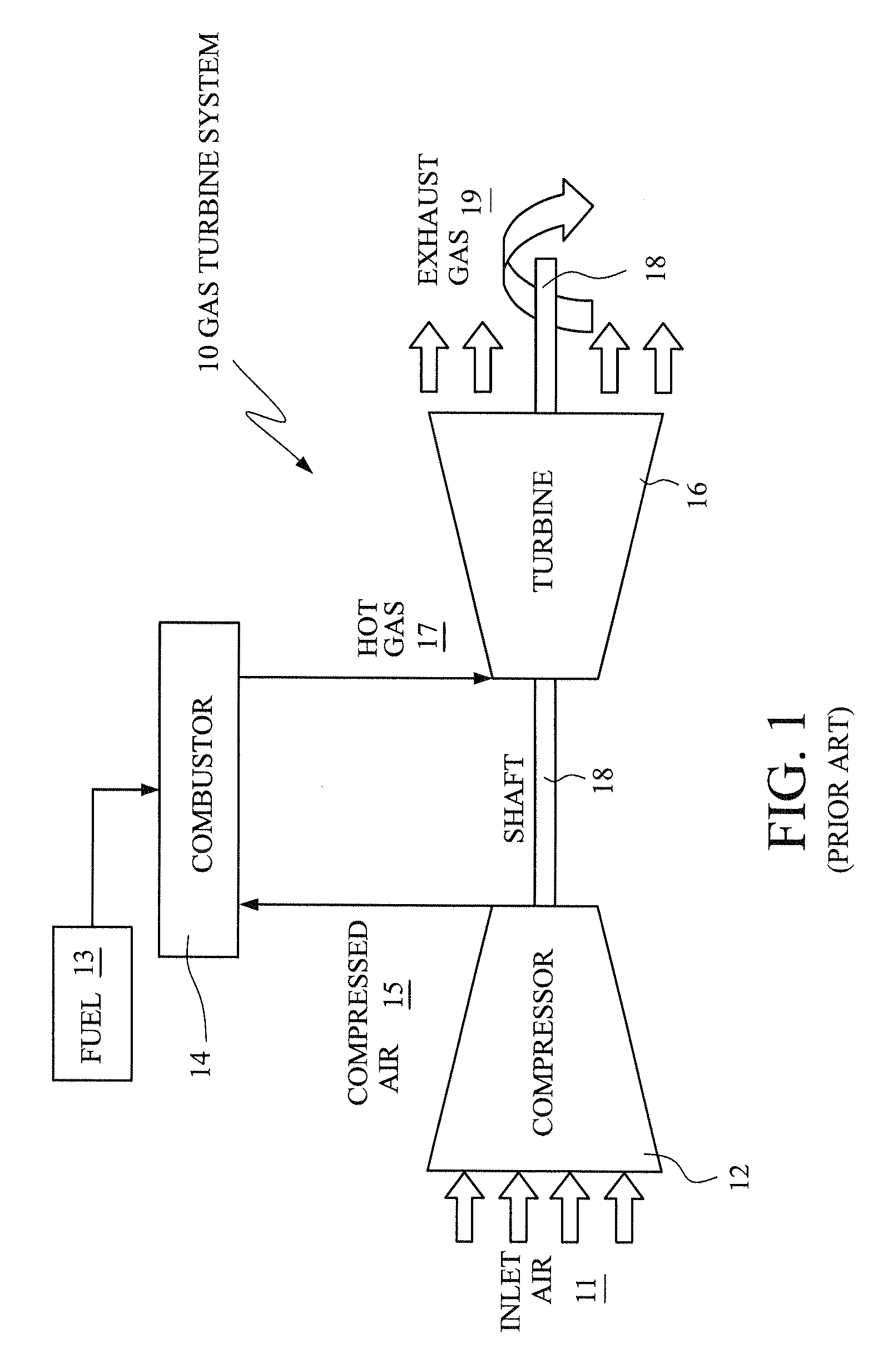
[0014]FIG. 1 is a simple diagram showing the components of a typical gas turbine system 10. The gas turbine system 10 includes a compressor 12, which compresses incoming air 11 to high pressure, a combustor 14, which burns fuel 13 so as to produce a high-pressure, high-velocity hot gas 17, and a turbine 16, which extracts energy from the high-pressure, high-velocity hot gas 17 entering the turbine 16 from the combustor 14 using turbine blades (not shown), so as to be rotated by the hot gas 17. As the turbine 16 is rotated, a shaft 18 connected to the turbine 16 is caused to be rotated as well. Finally, exhaust gas 19 exits the turbine 16.

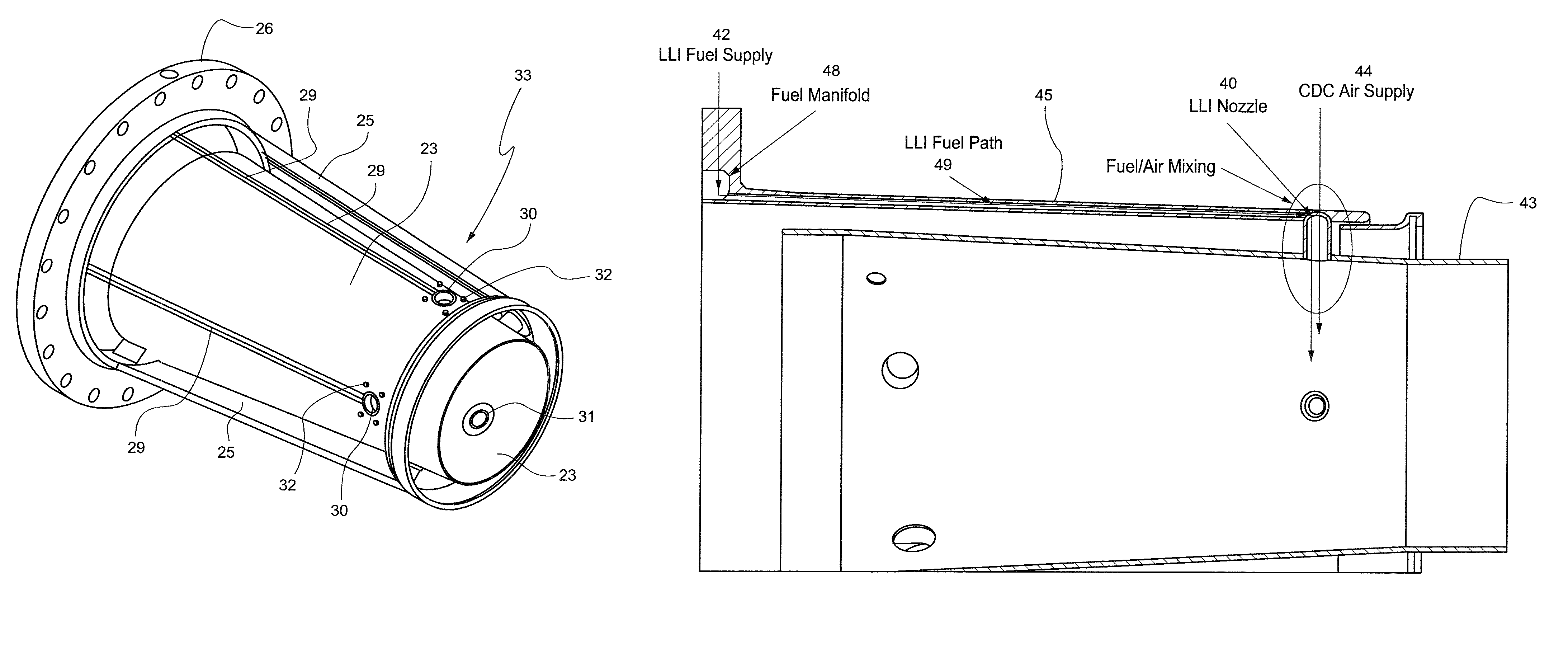
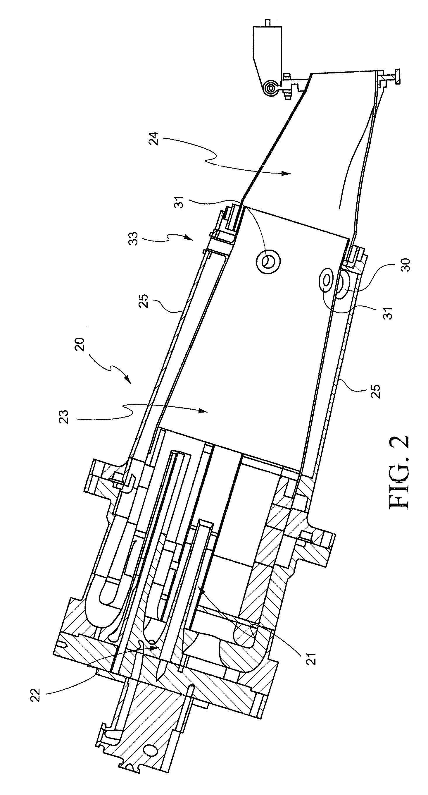
[0015]FIG. 2 is a partial side sectional view of a gas turbine combustor 20 including a late lean injection system according to the present invention. The combustor (combustor 14 in FIG. 1) includes a head end 22, which includes multiple premixing fuel nozzles 21, and a liner 23, which is connected to the head end 22, and in which supplied fuel is c...


PUM


Abstract

A late lean injection sleeve assembly allows the injection of fuel at the aft end of a gas turbine liner, before the transition piece, into the combustion gases downstream of a turbine combustor's fuel nozzles. The late lean injection enables fuel injection downstream of the fuel nozzles to create a secondary / tertiary (with quaternary injection upstream of the fuel nozzles) combustion zone while reducing / eliminating the risk of fuel leaking into the combustor discharge case. The fuel is delivered by the flow sleeve into one or more nozzles that mix the fuel with CDC air before injecting it into the combustor's liner.

Description

[0001]The present invention relates to turbines, and more particularly, to integrating a late lean injection into the combustion liner of a gas turbine and to a late lean injection sleeve assembly.BACKGROUND OF THE INVENTION[0002]Multiple designs exist for staged combustion in gas turbines, but most are complicated assemblies consisting of a plurality of tubing and interfaces. One kind of staged combustion in gas turbines is late lean injection (“LLI”) where the LLI injectors of the air / fuel mixture are located in a combustor far down stream to achieve improved NOx performance. NOx, or oxides of nitrogen, is one of the primary undesirable air polluting emissions produced by some gas turbines which burn conventional hydrocarbon fuels. The late lean injection is also used as an air bypass, which is useful to meet carbon monoxide or CO emissions during “turn down” or low load operation.[0003]Current late lean injection assemblies are expensive and costly for both new gas turbine units ...

Claims


Application Information

Patent Timeline
Patent Type & Authority Patents(United States)
IPC IPC(8): F02C3/00F02C7/22F02C1/04F02C7/224
CPCF23R3/06F23R3/283F23R3/286F23R3/346
Inventor BYRNE, WILLIAMMELTON, PATRICK BENEDICTCIHLAR, DAVID WILLIAMSTOIA, LUCAS
Owner GENERAL ELECTRIC CO
Why Eureka
Try Eureka