Resistive implant welding for adhesive curing for thermoplastic and thermoset applications

a technology of resistive implants and adhesive curing, which is applied in the direction of superstructure connections, domestic articles, lamination, etc., can solve the problems and achieve the effect of reducing process time and saving a substantial amount of energy

Active Publication Date: 2011-09-01
MAGNA INTERNATIONAL INC
View PDF11 Cites 16 Cited by
  • Summary
  • Abstract
  • Description
  • Claims
  • Application Information

AI Technical Summary

Benefits of technology

[0005]A structural component having a welded joint, where the structural component has two or more portions that are fused together at a weld line of the welded joint. An adhesive layer is placed between the two or more portions at the location of the weld line and a conductor is placed between the two or more portions in operable contact with the adhesive. Energy is transmitted through the conductor and into the adhesive layer to activate the adhesive layer and create the weld line that defines the welded joints between the two or more portions. The welded joint of the structural component allows energy to be injected into the adhesive layer via the conductor in order to cause the adhesive layer to activate from the inside of the adhesive outward. The conductor can be placed adjacent the adhesive layer or within the adhesive layer in order to cause the adhesive to be activated from the inside outward. This decreases the amount of process time and saves a substantial amount of energy needed to create the welded joint that would otherwise be required using traditional adhesive welding systems.

Problems solved by technology

This decreases the amount of process time and saves a substantial amount of energy needed to create the welded joint that would otherwise be required using traditional adhesive welding systems.

Method used


Image

  • Resistive implant welding for adhesive curing for thermoplastic and thermoset applications
  • Resistive implant welding for adhesive curing for thermoplastic and thermoset applications
  • Resistive implant welding for adhesive curing for thermoplastic and thermoset applications

Examples


Embodiment Construction

[0017]The following description of the preferred embodiment(s) is merely exemplary in nature and is in no way intended to limit the invention, its application, or uses.

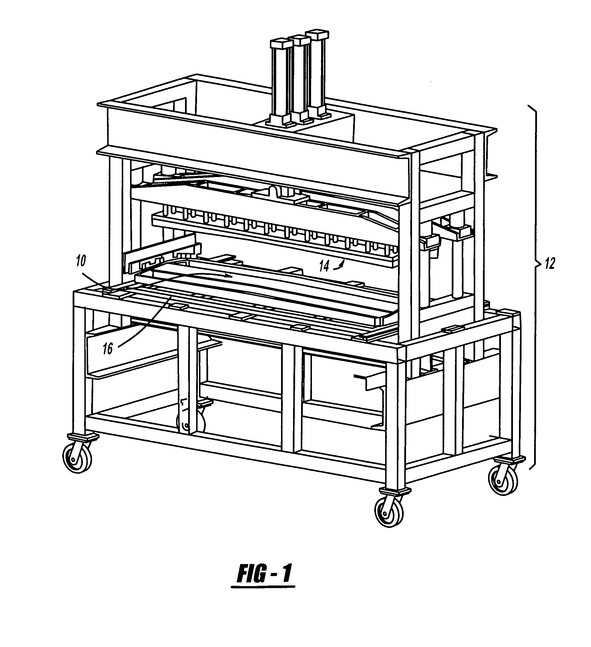
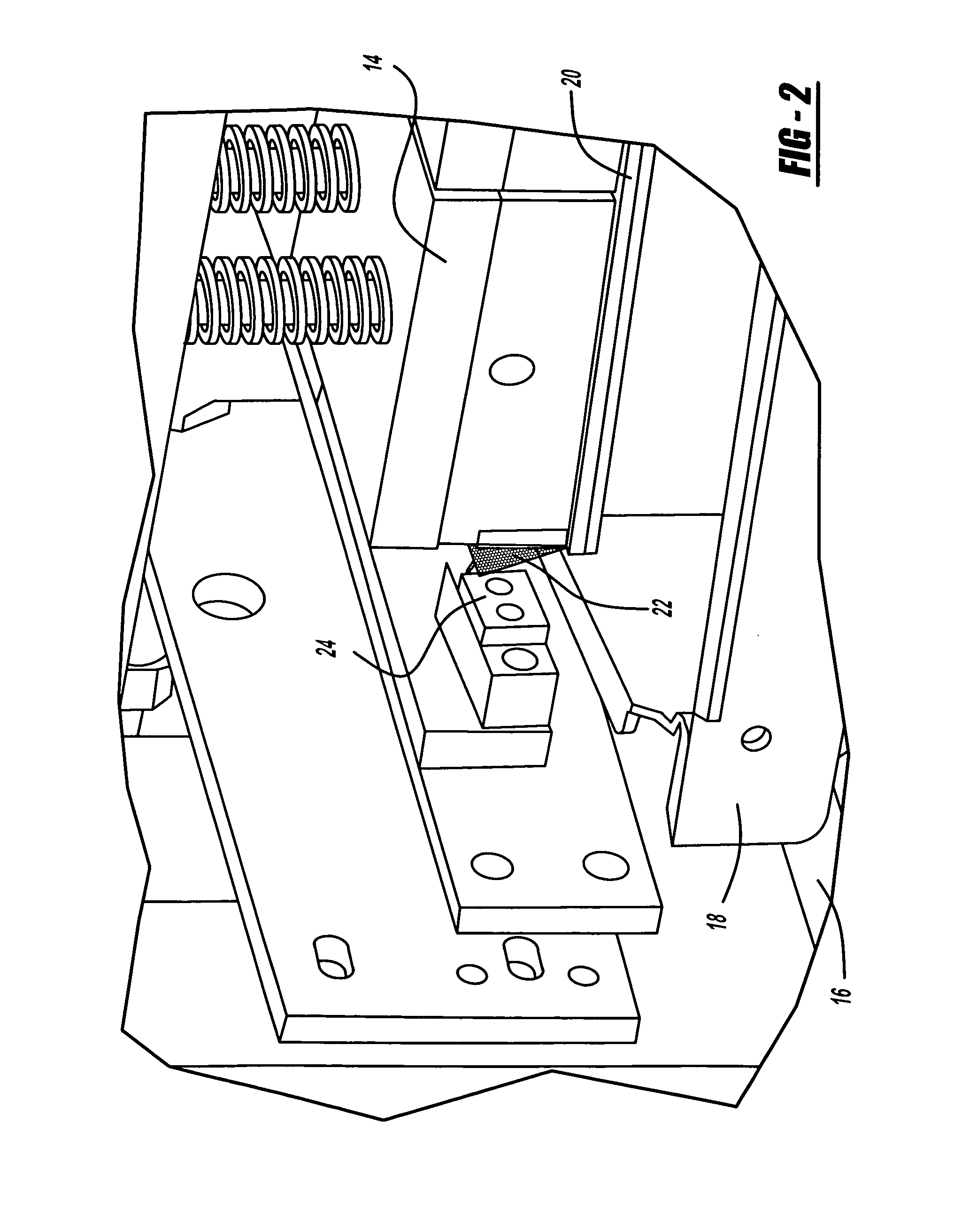
[0018]Referring now to FIGS. 1-2, 4 and 5 a method for forming a welded component using a hybrid resistive implant welding adhesive system. A structural component 10 is shown in the welding machine 12. The welding machine 12 has an upper platen 14 capable of moving vertically with respect to the structural component 10. The welding machine 12 also has a lower platen 16 upon which the structural component 10 rests. When the structural component 10 is to be welded the upper platen 14 will move vertically and press down against the structural component 10 and apply pressure. While the present exemplary embodiment of the invention describes the use of an upper platen 14 and lower platen 16, it is possible to reduce the number of fixtures required for forming the structural component 10 by eliminating the upper platen 14 a...


PUM

PropertyMeasurementUnit
surface areaaaaaaaaaaa
energyaaaaaaaaaa
pressureaaaaaaaaaa

Abstract

A welded joint for structural component having two or more portions fused together at a weld line. An adhesive layer is placed between the two or more portions at the location of the weld line and a conductor is placed between the two or more portions in operable contact with the adhesive. Energy is transmitted through the conductor and into the adhesive layer to activate the adhesive layer and create the weld line that defines the welded joints between the two or more portions. The welded joint of the structural component allows energy to be injected into the adhesive layer via the conductor in order to cause the adhesive layer to activate from the inside of the adhesive outward. The conductor can be placed adjacent the adhesive layer or within the adhesive layer in order to cause the adhesive to be activated from the inside outward.

Description

FIELD OF THE INVENTION[0001]The present invention relates to a hybrid resistive implant welding (RIW) adhesive technique for forming structural welds in structural applications.BACKGROUND OF THE INVENTION[0002]Welding together two or more components in structural applications is a common occurrence that requires the weld line to have a substantial amount of strength. Typically the components being welded together are made from the same materials; however, with the increase in the use of plastics in manufacturing, often different types of plastics and / or metals or other materials are welded together forming a joint. In order to form strong joints, traditional adhesive bonding systems have been used. Traditional adhesive bonding systems involve placing an adhesive between the two components that are to be welded together and then heating the adhesive area to cause the adhesive to activate and form a joint between the two parts. Heat activated adhesives are traditionally activated by h...

Claims


Application Information

Patent Timeline
Patent Type & Authority Applications(United States)
IPC IPC(8): B32B7/12B29C65/34B29C65/52B32B7/04B62D27/00
CPCB29C65/342Y10T428/17B29C65/3492B29C66/63B29C66/742B29C66/7465B29C66/7487B29K2021/00B29K2101/10B29K2101/12B29K2305/00B29K2309/08B29K2311/14B29L2031/3005B29L2031/724B29L2031/769B29L2031/7696B29L2031/7698B29C65/3432B29C65/3476Y10T428/197B29C66/5346B29C65/48B29C65/483B29C66/112B29C66/131Y10T428/192Y10T428/19B29C65/344B29C66/8322B29C66/721B29C66/73921B29C66/73941B29C66/71B29C66/8161Y10T428/31989Y10T428/31504Y10T428/31551Y10T428/31826Y10T428/31515Y10T428/31678Y10T428/31855
Inventor DYKE, DAVID SCOTTPANASIEWICZ, JEREMY ALANGRGAC, STEVEN
Owner MAGNA INTERNATIONAL INC
Why Eureka
Try Eureka