Vertically installed spar and construction methods

a vertical installation and wind turbine technology, applied in the field of vertical installation of wind turbine spars, can solve the problems of cost, few locations in the world, and the cost of conventional spars and offshore installation methods, and achieve the effect of cost-effectiveness

Active Publication Date: 2011-09-08
WANG JIN
View PDF9 Cites 14 Cited by
  • Summary
  • Abstract
  • Description
  • Claims
  • Application Information

AI Technical Summary

Benefits of technology

[0011]A vertically installed Spar-type floating wind turbine system for offshore Wind power generation and related construction methods are provided. The present invention can be assembled at a quayside vertically and towed at sea tog...

Problems solved by technology

Such conventional Spar-type floater and offshore installation method is costly.
However, there...

Method used


Image

  • Vertically installed spar and construction methods
  • Vertically installed spar and construction methods
  • Vertically installed spar and construction methods

Examples


Embodiment Construction

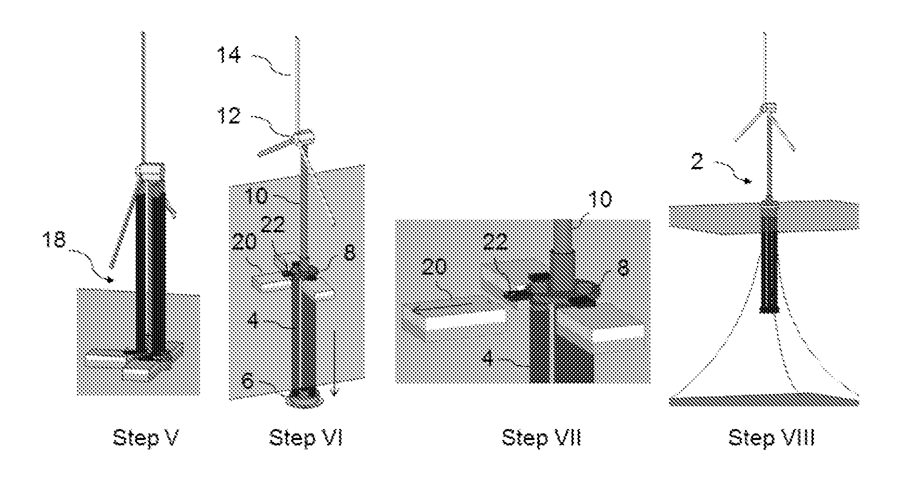
[0022]Preferred embodiments of the present invention are shown in FIG. 5 through 10 above with detailed description as follows.

[0023]With reference to FIG. 5, a floating wind turbine system 2 in operating configuration includes a plurality of vertically extending columns 4; a ballast tank 6 coupled to the lower end of each of the columns 4; a top deck 8 coupled to the upper end of each of the columns; a wind turbine assembly, comprising a tower 10, a nacelle 12 and rotor blades 14, supported by the top deck; and a plurality of mooring lines 16 linking the said floating system to the sea floor. The floating wind turbine system 2 has a referred range of in-service operating draft of 80 to 120 meters. The columns 4 are empty and, the lower column segment contains a ballast material most commonly sea water. With respect to the columns 4, the preferred number of columns is three and the preferred cross-section is circular which may be of same diameter throughout Or of different diameters...


PUM

PropertyMeasurementUnit
Stabilityaaaaaaaaaa

Abstract

A vertically installed Spar-type floater for offshore wind turbine and related construction method are provided. The floating system is a gravity stabilized deep-draft floater including a plurality of vertically extending columns, each column containing a ballast material; a ballast tank coupled to the lower end of each of the columns; a top deck having a plurality of through-bores approximate its periphery coupled to the upper end of each of the columns; a wind turbine assembly supported by the top deck at the center; a plurality of mooring lines linking the floating system to the sea floor. The floating system has a temporary vertically towing configuration which: allows the entire, floating wind turbine system to be assembled at a quayside and towed vertically to an offshore site, and self-installed into operating configuration.

Description

CROSS-REFERENCE TO RELATED APPLICATIONS[0001]This present application claims the benefits of priority from the U.S. provisional application No. 61 / 310,473, entitled “VERTICALLY INSTALLED SPAR FOR OFFSHORE WIND TURBINES AND CONSTRUCTION METHODS”, filed on Mar. 4, 2010.STATEMENT REGARDING FEDERALLY SPONSORED RESEARCH OR[0002]Not applicable.REFERENCES[0003](1) U.S. Pat. No. 4,702,321, Filing date: Sep. 20, 1985, Issue date: Oct. 27, 1987[0004](2) U.S. Pat. No. 6,263,824, Filing date: Dec. 23, 1997. Issue date: Jul. 24, 2001[0005](3) Top Plants: Hywind Floating Wind Turbine, North Sea, Norway, Power Magazine Article, Dec. 1, 2009[0006](4) U.S. Pat. No. 7,819,073, Filing date: Jun. 2, 2006, Issue date: Oct. 26, 2010[0007](5) U.S. Pat. No. 7,612,462, Filing date: Apr. 24, 2008, Issue date: Nov. 3, 2009FIELD OF INVENTION[0008]Embodiments of present invention relate generally to the field of floating offshore wind turbines for offshore wind power generation. More particularly, embodiments o...

Claims


Application Information

Patent Timeline
IPC IPC(8): B63B35/44B63B21/56B63B21/60B23P11/00
CPCY02E10/727B23P11/00Y10T29/49826B63B21/60B63B35/44B63B21/56F05B2240/93F05B2240/9151F03D13/25Y02E10/72
Inventor WANG, JIN
Owner WANG JIN
Why Eureka
Try Eureka