

Infrared zooming lens
a zoom lens and infrared technology, applied in the field of infrared zoom lenses, can solve the problems of inability to use, troublesome zoom lens aberration compensation, no dynamic focusing control, etc., and achieve the effect of inhibiting aberration variation and facilitating compensation of field curvatur
- Summary
- Abstract
- Description
- Claims
- Application Information
AI Technical Summary
Benefits of technology
Problems solved by technology
Method used
Image

Examples
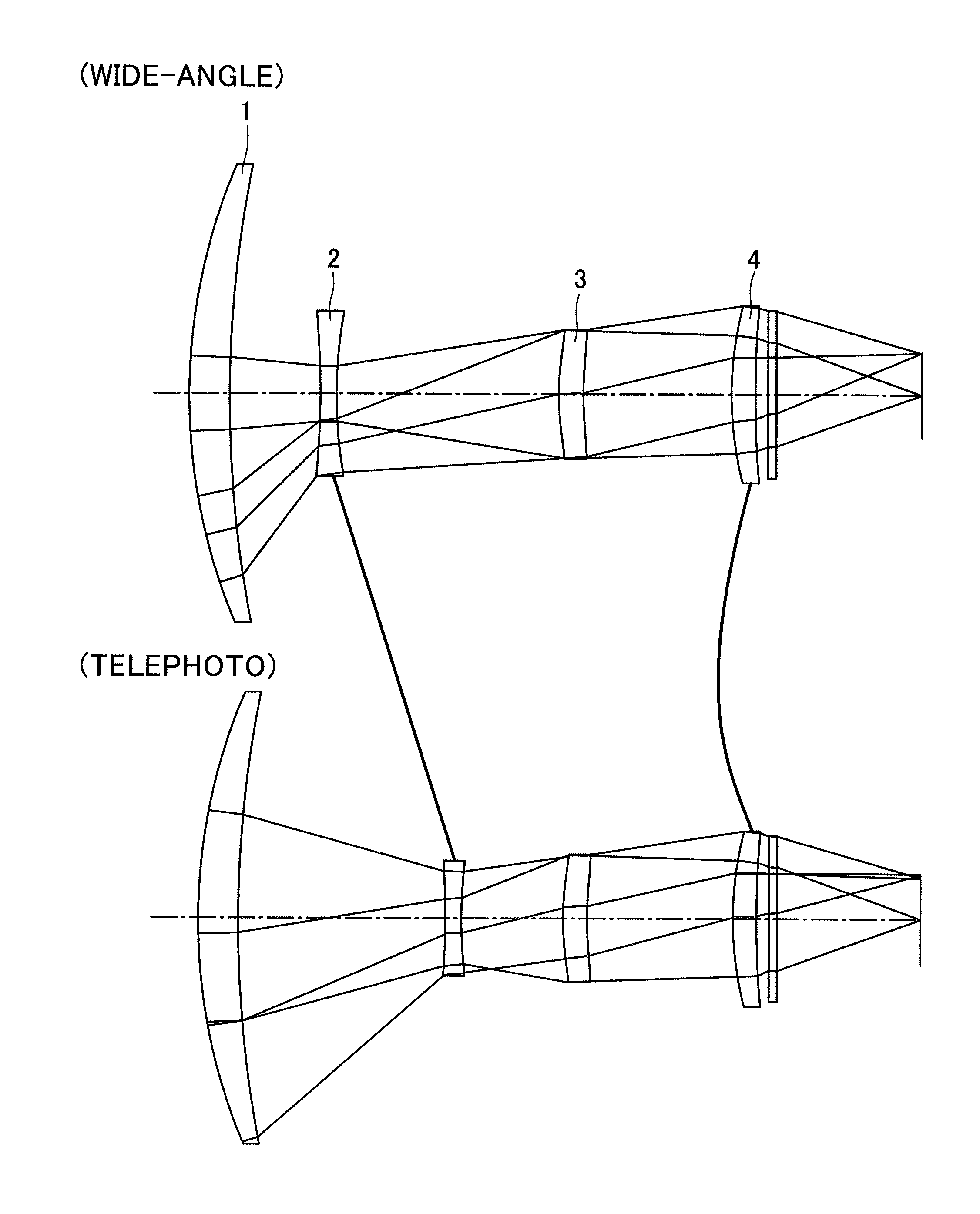
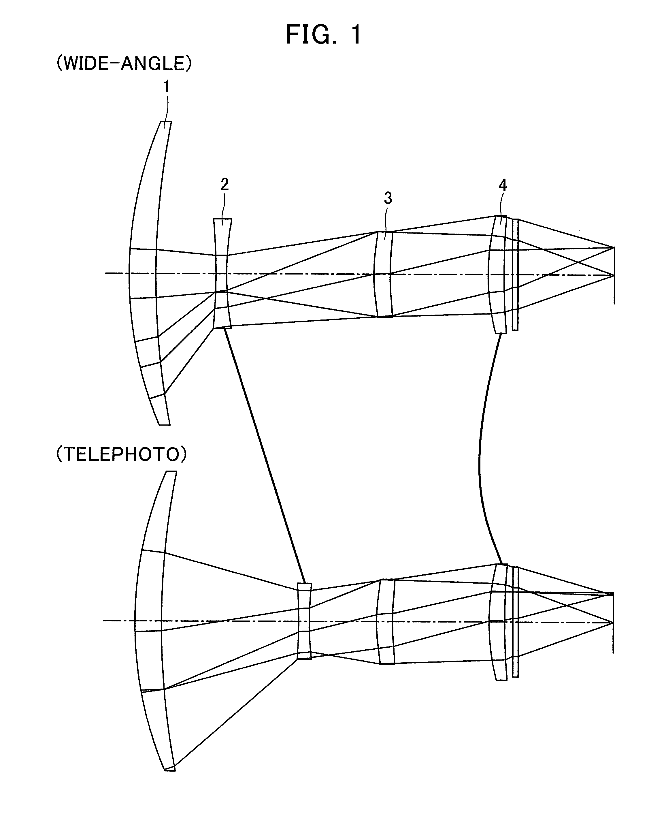
embodiment 1
[0071]Data on a first preferred embodiment of an infrared zoom lens according to the present invention will be set forth below:
SURFACE#RDGLASS181.00005.0000GERMANIUM2ASPH168.0078D(2)3ASPH−101.61332.0000GERMANIUM4ASPH67.9744D(4)5STOP37.89443.0000GERMANIUM6ASPH51.6729D(6)749.00003.0000GERMANIUM8ASPH168.5145D(8)90.00001.0000GERMANIUM100.0000D(10)
[0072]D(i) in the table above denotes where the distance between the adjacent lens groups varies as the focal length is varied (i is the number of the rearmost surface in one lens group).
[0073]Any of numbers identifying lens surfaces suffixed with characters ASPH designates an aspherical surface. A formula representing the aspherical surface is given as follows:
X=H2 / R1+1-(ɛH2 / R2)+AH2+BH4+CH6+DH8+EH10
where H is a height of the aspherical surface from and perpendicular to the optical axis, X(H) is a varied amount of the height H relative to a varied departure with the apex of the aspherical surface at the origin, R is a paraxial radius of curvatu...
embodiment 2
[0075]Data on the optical components in a second preferred embodiment of the infrared zoom lens are set forth below:
SURFACE#RDGLASS1217.48559.0000GERMANIUM2ASPH418.5663D(2)3ASPH−240.70844.5000GERMANIUM4ASPH430.2428D(4)5STOP67.81177.0000GERMANIUM6ASPH92.1746D(6)737.81535.0000GERMANIUM8ASPH44.8231D(8)90.00001.0000GERMANIUM100.0000D(10)
Data on the Aspherical SurfacesSURFACE#0(EP)2(A)4(B)6(C)8(D)10(E)218.54490.00000E+000−3.13306E−008−2.42866E−0120.00000E+0000.00000E+0003−99.00130.00000E+0006.13608E−007−1.92476E−0091.30313E−0120.00000E+000483.49770.00000E+0001.26877E−006−2.48226E−0091.49943E−0120.00000E+0005−1.17160.00000E+0001.61863E−0076.75443E−010−9.52129E−0130.00000E+00066.20110.00000E+000−1.52912E−0066.19667E−010−1.65398E−0120.00000E+00081.23580.00000E+0001.03673E−0072.58085E−0100.00000E+0000.00000E+000
Focal LengthWIDE-ANGLETELEPHOTO35.01100.00
[0076]Distance Between the Adjacent Lens Groups During the Zooming
WIDE-ANGLETELEPHOTOD(2)12.50065.536D(4)63.03610.000D(6)51.58054.574D(8)8.81...
embodiment 3
[0077]Data of the optical components of a third preferred embodiment of the infrared zoom lens are set forth below:
SURFACE#RDGLASS181.00005.0000GERMANIUM2146.8796D(2)3ASPH−116.93342.0000GERMANIUM4ASPH83.5380D(4)5STOP29.93223.0000GERMANIUM6ASPH35.9505D(6)749.00003.0000GERMANIUM8ASPH157.5165D(8)90.00001.0000GERMANIUM100.0000D(10)
Data on the Aspherical SurfacesSURFACE#0(EP)2(A)4(B)6(C)8(D)10(E)376.47930.00000E+0002.32912E−0057.25919E−0080.00000E+0000.00000E+0004−99.00330.00000E+0003.28211E−0053.72487E−0080.00000E+0000.00000E+0005−10.90640.00000E+000−8.83597E−006−4.11010E−0070.00000E+0000.00000E+0006−0.45660.00000E+000−7.53352E−005−1.59835E−0070.00000E+0000.00000E+0008101.06580.00000E+0003.21451E−006−8.01724E−0090.00000E+0000.00000E+000
Focal LengthWIDE-ANGLETELEPHOTO14.0839.99
[0078]Distance Between the Adjacent Lens Groups During the Zooming
WIDE-ANGLETELEPHOTOD(2)10.70628.286D(4)31.22413.645D(6)15.62815.623D(8)1.4111.416D(10)17.99617.996
PUM
 Abstract
Description
Claims
Application Information