
Selective Repositioning and Rotation Wavelength Beam Combining System and Method

a wavelength beam and wavelength beam technology, applied in lasers, laser details, instruments, etc., can solve the problems of poor spectral utilization, limited output beam quality, and high utilization ra

Active Publication Date: 2011-09-08
PANASONIC OF NORTH AMERICA
View PDF12 Cites 82 Cited by
  • Summary
  • Abstract
  • Description
  • Claims
  • Application Information

AI Technical Summary

Benefits of technology

"The patent describes how to control the rotation and position of electromagnetic beams emitted from various sources. This is useful for combining beams of different wavelengths in one-dimensional or two-dimensional arrays. The systems and methods described can be used with emitters that have a fixed position relative to other emitters. The technical effect of this patent is the ability to precisely control the orientation and pattern of emitted beams, which can improve the efficiency and accuracy of wavelength beam combining systems."

Problems solved by technology

Furthermore, when broad-area laser elements are used the spectral utilization is poor.
Furthermore, since beam combining is performed along the stacking dimension or near diffraction-limited dimension spectral utilization is high.
However, one of the main drawbacks of this implementation is the output beam quality is limited to the beam quality of a single beam combining element or a single bar.
The brightness of such a system is barely adequate for some applications like industrial laser cutting of thin and thick sheet metal, including stainless steel, mild steel, aluminum, and copper.
However, they are less readily available at a much higher cost per unit of output power as compared with standard diode laser bars.

Method used


Image

  • Selective Repositioning and Rotation Wavelength Beam Combining System and Method
  • Selective Repositioning and Rotation Wavelength Beam Combining System and Method
  • Selective Repositioning and Rotation Wavelength Beam Combining System and Method

Examples


Embodiment Construction

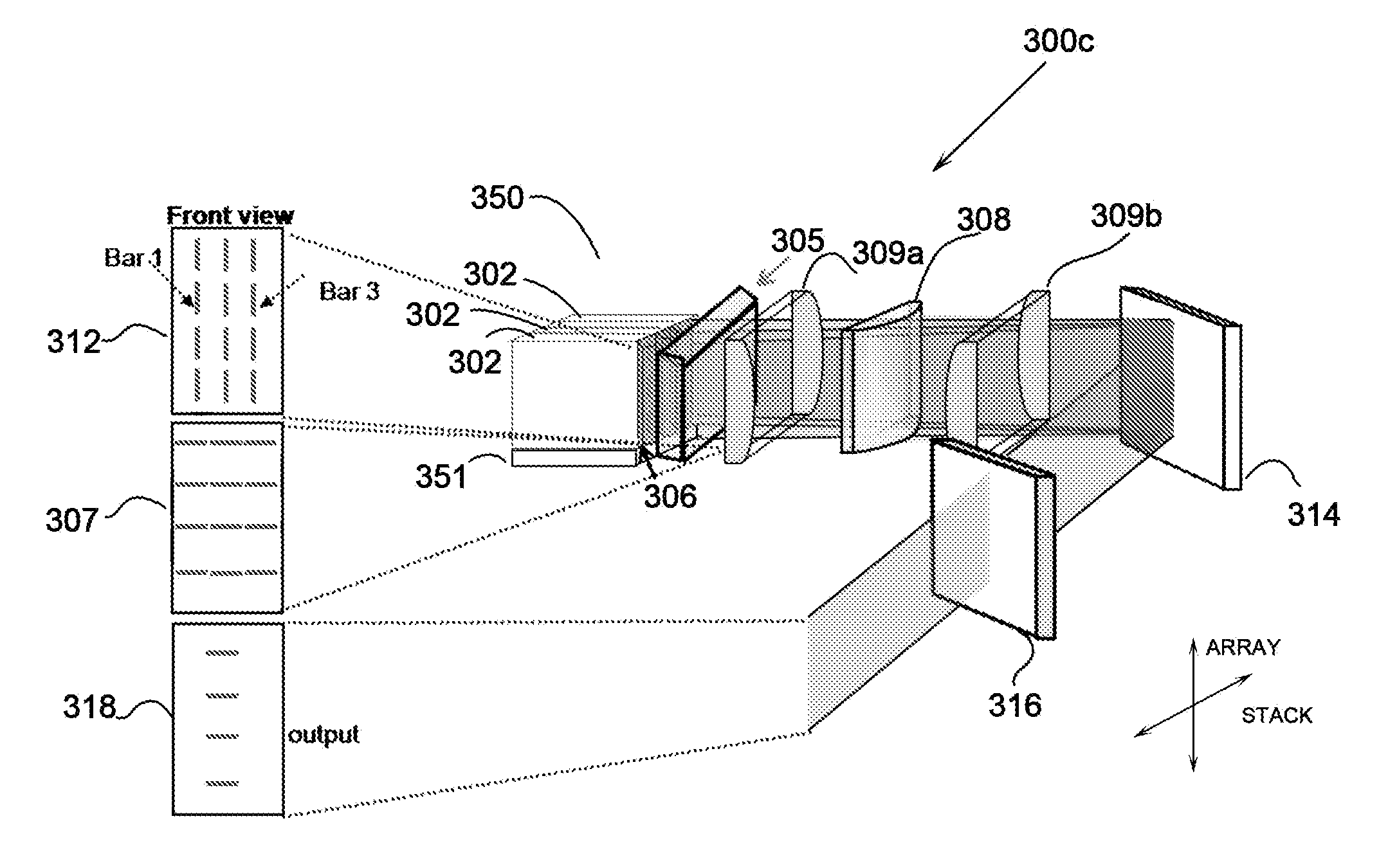
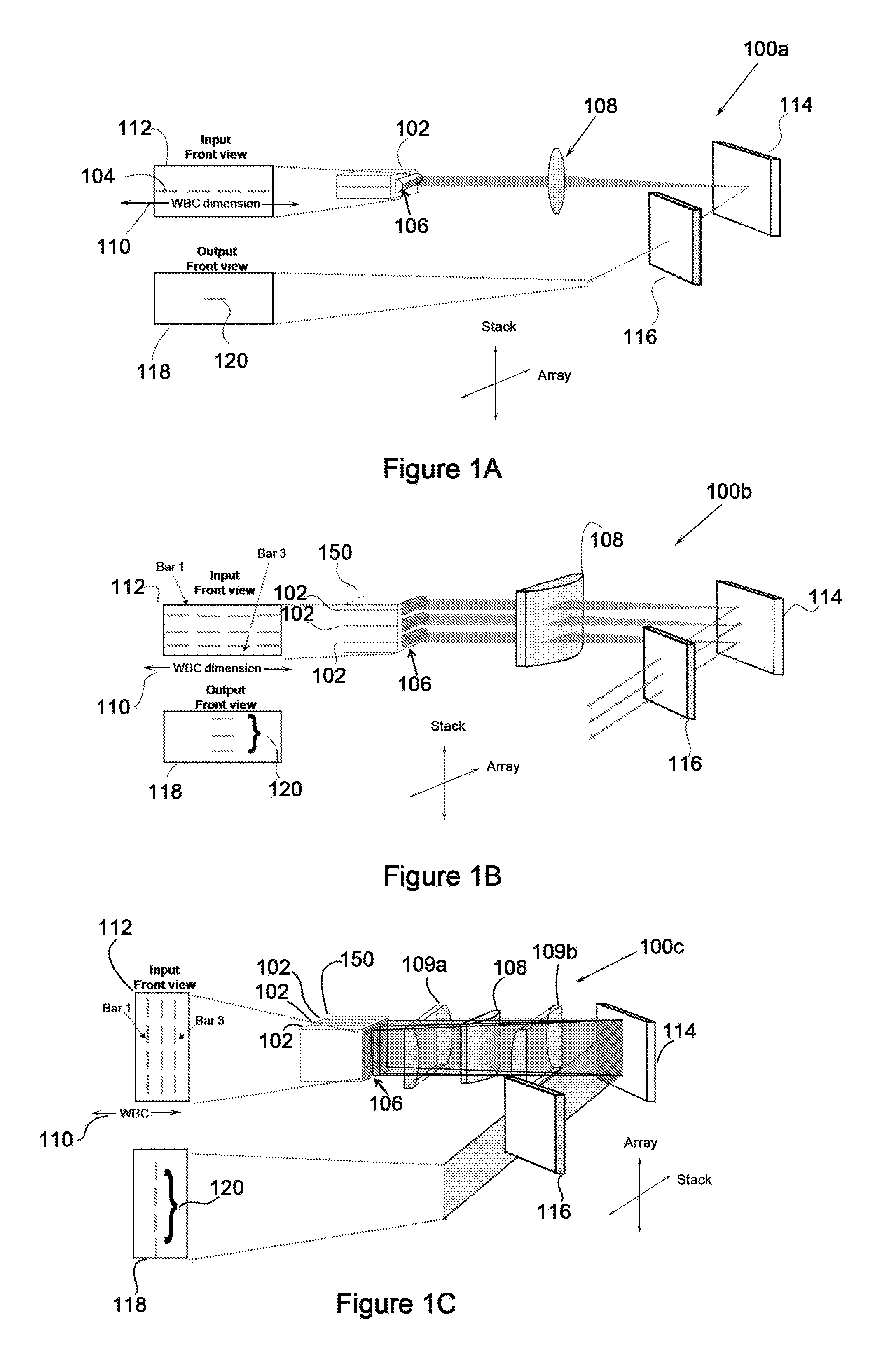
[0026]Aspects and embodiments relate generally to the field of scaling laser sources to high-power and high-brightness using an external cavity and, more particularly, to methods and apparatus for external-cavity beam combining using both one-dimensional or two-dimensional laser sources. In one embodiment the external cavity system includes one-dimensional or two-dimensional laser elements, an optical system, a dispersive element, and a partially reflecting element. An optical system is one or more optical elements that perform two basic functions. The first function is to overlap all the laser elements along the beam combining dimension onto a dispersive element. The second function is to make sure all the elements along the non beam combining dimension are propagating normal to the output coupler. Care must be taken to ensure that the optical system introduces as little loss as possible. As such, these two functions will enable a single resonance cavity for all the laser elements....


PUM


Abstract

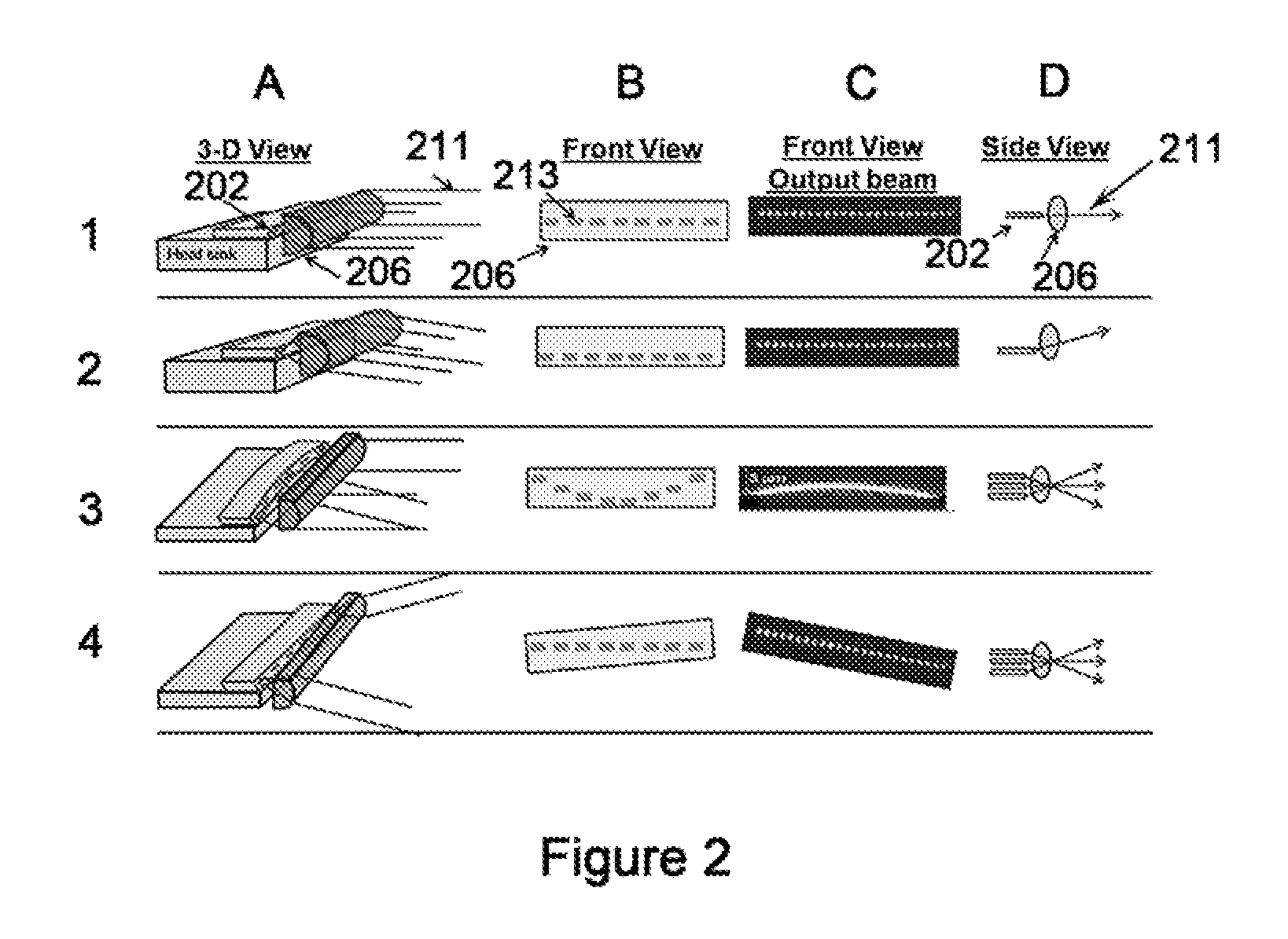
A system and method for reconfiguring a plurality of electromagnetic beams to take advantage of various wavelength beam combining techniques. The reconfiguring of beams includes individual rotation and selective repositioning of one or more beams with respect to beam's original input position.

Description

CROSS-REFERENCE TO RELATED APPLICATIONS[0001]This application claims priority under 35 U.S.C. §119 to the following U.S. Provisional Patent Applications, each of which is hereby incorporated by reference in its entirety: U.S. Ser. No. 61 / 310,777 filed Mar. 5, 2010; U.S. Ser. No. 61 / 310,781 filed Mar. 5, 2010, and U.S. Ser. No. 61 / 417,394 filed Nov. 26, 2010.BACKGROUND OF THE INVENTION[0002]1. Field of the Invention[0003]The present embodiments relate generally to laser systems and more particularly to wavelength beam combining systems and methods.[0004]2. Description of the Prior Art[0005]Wavelength beam combining (WBC) is a method for scaling the output power and brightness from laser diode bars, stacks of diode bars, as well as other lasers arranged in one or two-dimensional array.[0006]WBC methods have been developed to combine beams along the slow dimension of each emitter as well as the fast dimension of each emitter. See for example, U.S. Pat. Nos. 6,192,062, 6,208,679 and 201...

Claims


Application Information

Patent Timeline
Patent Type & Authority Applications(United States)
IPC IPC(8): G02B27/10
CPCG02B27/0905G02B19/0014H01S3/0675H01S3/094053H01S3/094057H01S3/09408H01S3/094096H01S3/09415H01S3/1618H01S3/175H01S3/176H01S5/0057H01S5/4012H01S5/405H01S5/4062H01S5/4087H01S2301/03G02B19/0057G02B19/0028H01S3/06733
Inventor CHANN, BIENHUANG, ROBIN
Owner PANASONIC OF NORTH AMERICA
Learn More