Vehicle light

a technology for vehicles and light sources, applied in fixed installations, light and heating equipment, transportation and packaging, etc., can solve the problems of uneven intensity distribution, uneven luminance chromaticity, and disadvantageous interfacial peeling, and achieve the effect of preventing or suppressing uneven luminance chromaticity or uneven intensity distribution of light, and preventing or suppressing the occurrence of interfacial peeling

Inactive Publication Date: 2011-09-08
STANLEY ELECTRIC CO LTD
View PDF4 Cites 56 Cited by
  • Summary
  • Abstract
  • Description
  • Claims
  • Application Information

AI Technical Summary

Benefits of technology

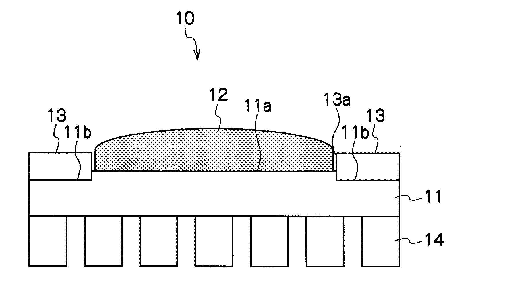
[0020]The presently disclosed subject matter was devised in view of these and other problems and features and in association with the conventional art. According to an aspect of the presently disclosed subject matter, a vehicle light can prevent or suppress the uneven luminance chromaticity or uneven intensity distribution of light caused by the reflection of blue laser beams emitted from a laser light source and reflected by the surface of a metal plate around a fluorescent material.
[0021]According to another aspect of the presently disclosed subject matter, a vehicle light can prevent or suppress the occurrence of interfacial peeling caused by the difference of thermal expansion coefficient between a fluorescent material and a member to which the fluorescent material is disposed.

Problems solved by technology

Accordingly, this may cause uneven luminescent chromaticity as well as uneven intensity distribution.
Accordingly, when the turning-on and turning-off are repeated (namely, the temperature increase / decrease is repeated), interfacial peeling may disadvantageously occur.

Method used


Image

  • Vehicle light
  • Vehicle light
  • Vehicle light

Examples


modified example 1

[0104]The vehicle light 100 in accordance with a modified example 1 can include, as shown in FIG. 19, the light emitting portion 10, the laser optical system 20, and a reflecting surface 40, and the like.

[0105]The reflecting surface 40 can be a revolved parabolic reflecting surface having a focus disposed at or near (i.e., substantially at) the side 12a of the fluorescent material 12 that corresponds to the bright / dark boundary line in the light distribution pattern.

[0106]According to the present modified example 1, the reflection suppressing member 13 can be a carbon plate shown in FIG. 15B, for example, having a horizontally long elliptic opening 13a where the fluorescent material 12 can be disposed. This configuration can provide a reflective type (or parabola type) vehicle light that can form a high beam light distribution pattern without (or almost without) uneven luminance chromaticity or uneven intensity distribution of light.

[0107]Alternatively, the reflection suppressing me...

modified example 2

[0108]The vehicle light 100 in accordance with the modified example 2 can include, as shown in FIG. 20, the light emitting portion 10, the laser optical system 20, the projector lens 50, a reflecting surface 51, a light shielding member 52 disposed between the projector lens 50 and the reflecting surface 51, and the like.

[0109]The projector lens 50 can have a focus disposed at or near the upper edge of the light-shielding member 52.

[0110]The reflecting surface 51 can be a revolved elliptic reflecting surface having a first focus disposed at or near the side 12a of the fluorescent material 12 corresponding to the bright / dark boundary and a second focus disposed at or near the upper edge of the light-shielding member 52. In the elliptic reflecting surface, a parabola appears in a longitudinal cross section and a part of a ellipsoid appears in a horizontal cross section.

[0111]For example, the reflecting surface 51 can be configured such that the image of the fluorescent material 12 at ...


PUM


Abstract

A vehicle light can prevent or suppress uneven luminance chromaticity or uneven intensity distribution of light caused by reflection of blue laser beams emitted from a laser light source and reflected by the surface of a metal plate located around fluorescent material. The vehicle light can include a metal plate, a fluorescent material provided on a surface of the metal plate. The fluorescent material can serve as a light source for emitting light beams as a result of excitation by a blue laser beam. A laser light source can be configured to emit the blue laser beam to be incident on the fluorescent material. A reflection suppressing member can be provided to cover the surface of the metal plate around the fluorescent material and can be configured to suppress the reflection of the blue laser beam emitted by the laser light source.

Description

[0001]This application claims the priority benefit under 35 U.S.C. §119 of Japanese Patent Applications No. 2010-045320 filed on Mar. 2, 2010 and No. 2010-062585 filed on Mar. 18, 2010, which are hereby incorporated in their entirety by reference.TECHNICAL FIELD[0002]The presently disclosed subject matter relates to a vehicle light, and in particular, to a vehicle light utilizing a light source in which a blue laser beam and a fluorescent material that can emit light by being excited by the blue laser beam are used.BACKGROUND ART[0003]In the conventional technical field relating to vehicle lights, a brighter light source has been desired to illuminate distant areas with high intensity light beams at night. One example is described in Japanese Patent Application Laid-Open No. 2005-150041 (corresponding to U.S. Pat. No. 7,165,871).[0004]The present inventors have focused on the point in which the brightness (or intensity) of a fluorescent material (for example, YAG fluorescent materia...

Claims


Application Information

Patent Timeline
Patent Type & Authority Applications(United States)
IPC IPC(8): F21S8/10
CPCF21S48/214F21S48/1145F21S41/16F21S41/176F21S43/16
Inventor KOIKE, TERUOLIANG, JI HAO
Owner STANLEY ELECTRIC CO LTD
Why Eureka
Try Eureka