Method and apparatus for the production of nuclear fusion

a nuclear fusion and apparatus technology, applied in the direction of nuclear targets, nuclear reactors, greenhouse gas reduction, etc., can solve the problems of large amount of charged particles, extreme difficulty in reaction containment, and prior art is incapable of utilizing the known highly desirable aneutronic fusion reactions, etc., to achieve low efficiency, increase the number of fusion events, and improve efficiency

Inactive Publication Date: 2011-09-08
PEARSON TIMOTHY RAYMOND
View PDF5 Cites 21 Cited by
  • Summary
  • Abstract
  • Description
  • Claims
  • Application Information

AI Technical Summary

Benefits of technology

[0009]The invention provides a central scattering block, sandwiched between two thin conductive plates, into which reactants are fired lengthwise at fusion energies. This structure is further placed within a conductive vacuum chamber, and isolated from said chamber by means of insulating supports. A plurality of thin conductive collection elements are suspended from the floor and ceiling of the vacuum chamber in such a way at to capture the majority of charged particles ejected from the scattering block. Each collection element is isolated from the vacuum chamber by means of insulating supports. The combination of the charged collection elements and vacuum chamber walls generates a high electric field that acts to recirculate ejected unfused reactants back into the scattering block, dramatically improving fusion efficiency.
[0014]At least one reactant storage element is provided outside of the vacuum chamber, connected to said chamber by means of a valve that controls the rate of reactant entry.
[0015]Without limiting the scope of the invention, several problems in the prior art and their solution in this invention are discussed herein. With respect to the problem of low efficiency, several advancements are made. The present invention first increases the number of fusion events that occur during the initial critical moments of a reactant ion's flight by firing said reactant ion into a solid block of reactant. This decreases loss due to Bremsstrahlung and related effects that would normally occur as prematurely ejected reactant ions are subsequently redirected back into the reaction area of the device, usually many thousands of times. The present invention also increases efficiency by providing two distinct areas of particle flow, each area consisting of particles of similar energy traveling along largely the same trajectories, so as to avoid unwanted interaction between particles and related energy loss. Also, any prematurely ejected, unfused particles are recirculated several times by the electric fields present around the solid reactant, and the small vertical dimension of the solid form reactant allows released fusion products to escape the solid reactant with very low loss. This recirculation is possible because the minimum likely energy of the fusion products is much greater than the maximum possible energy of the reactant ions, and therefore the reactant ions can be electrostatically confined to an area near the solid reactant.

Problems solved by technology

Additionally, certain reactants release large amounts of charged particles when fused.
Additionally, the prior art is incapable of utilizing the known highly desirable aneutronic fusion reactions, such as that between protons and boron-11, as reported in “Potentiality of the Proton-Boron Fuel for Controlled Thermonuclear Fusion” by Didier C. Moreau in 1976.
This class of device has a number of drawbacks and limitations, including but not limited to: extreme difficulty of reaction containment, inability to utilize solid reactants efficiently, and general radiative and Bremsstrahlung energy loss prohibiting the use of known desirable aneutronic fusion reactions.
Unfortunately, it suffers from an abysmal efficiency due to grid collisions, a relative scarcity of fusion events, and no direct way to convert the released energy into electricity.
However, pyroelectric fusion differs from the present invention in many important aspects, some of which are listed here: means of generating reactant particles, target structure, target angle with respect to the incident reactant beam, absence of reactant recirculation, an inability to use multiple reactants, an inability to refuel the reactor while it is operating, low fusion efficiency, undesirable sputtering of target material on vacuum chamber walls, and an absence of collection elements with which to convert the fusion products to usable electrical power.

Method used


Image

  • Method and apparatus for the production of nuclear fusion
  • Method and apparatus for the production of nuclear fusion
  • Method and apparatus for the production of nuclear fusion

Examples


Embodiment Construction

[0029]While the design and usage of specific embodiments are discussed below, it should be understood that these discussions do not limit the scope of this invention, and that the broad concepts which are part of this invention may be usable in other specific embodiments which are not discussed below.

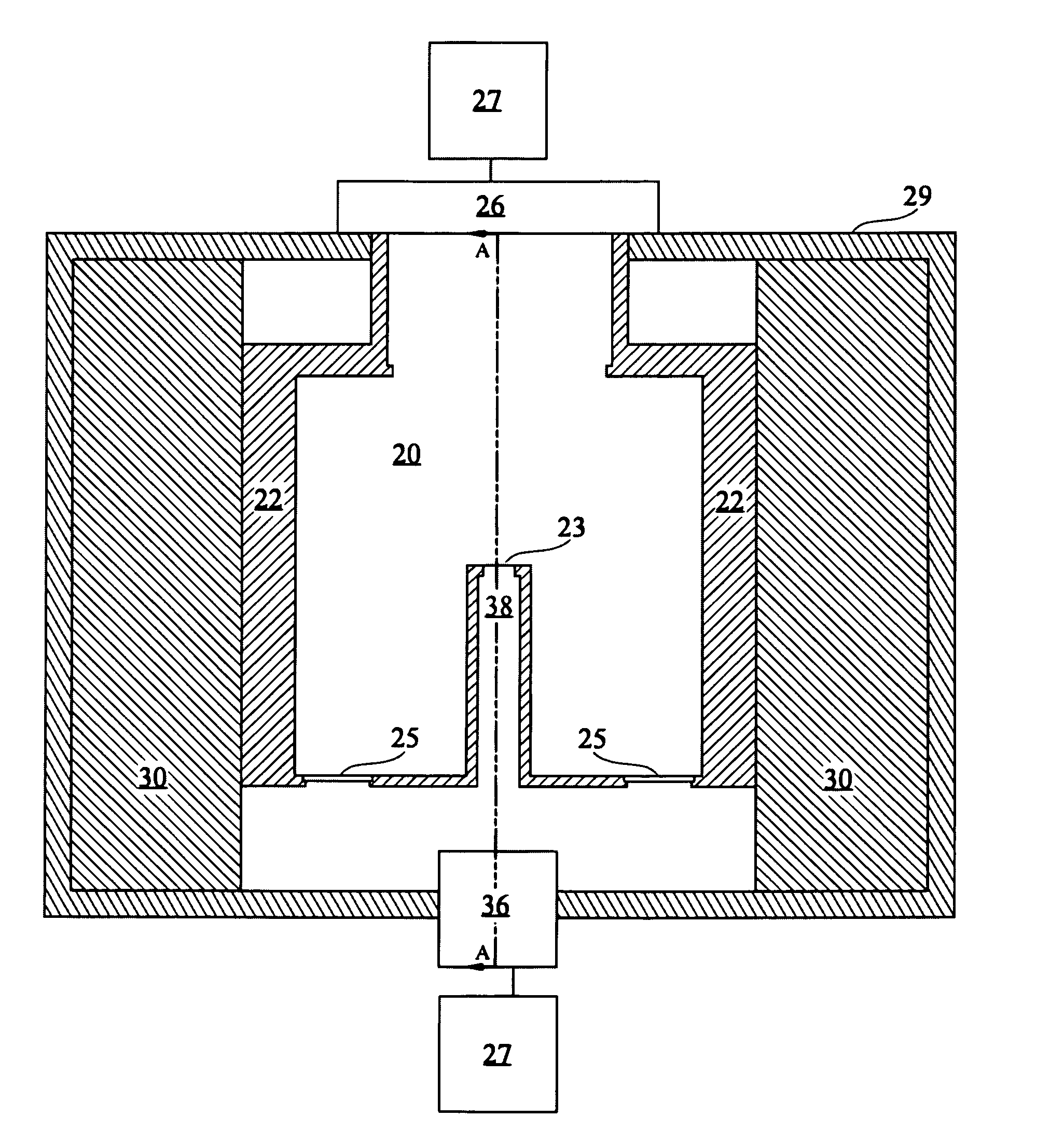
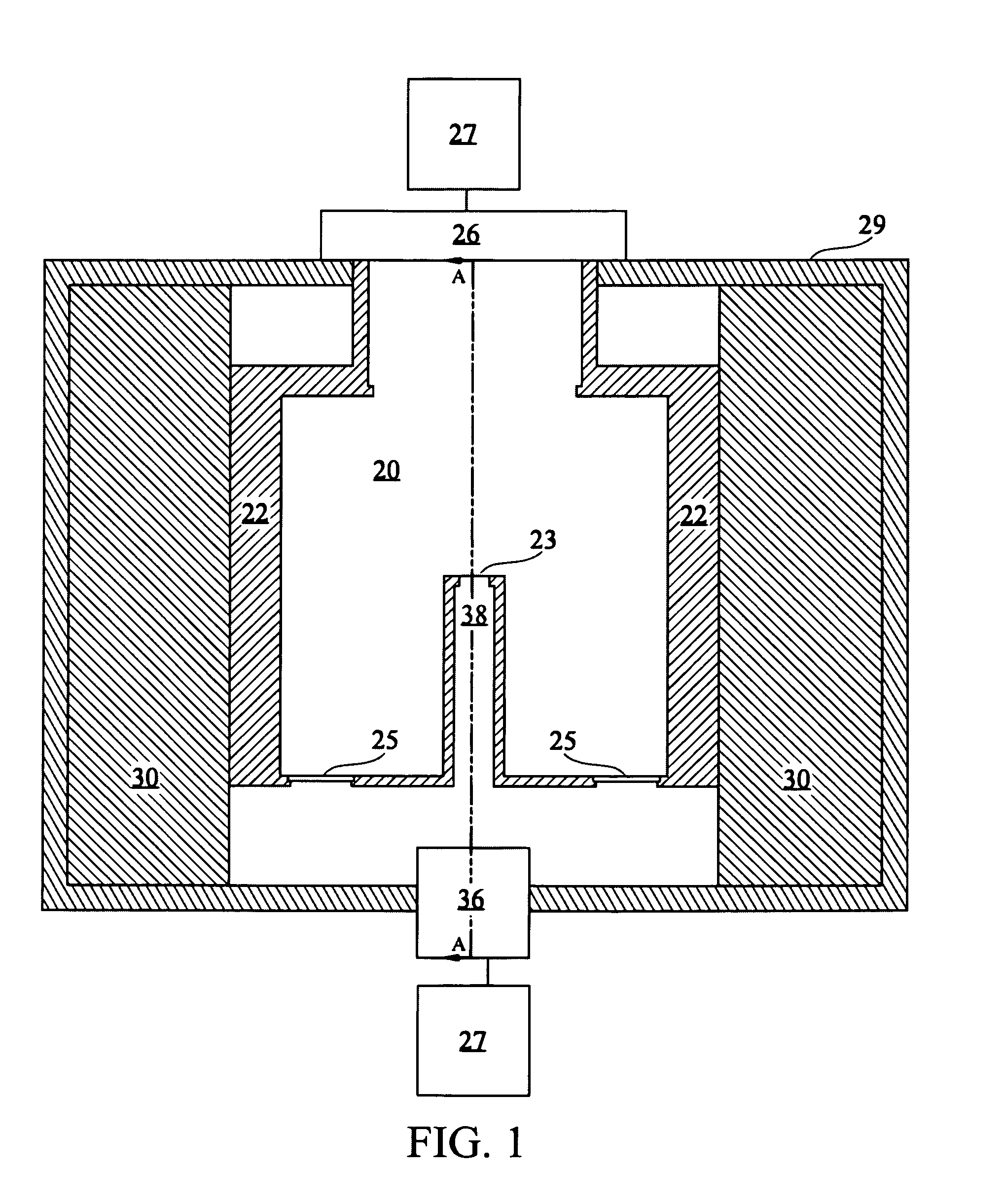
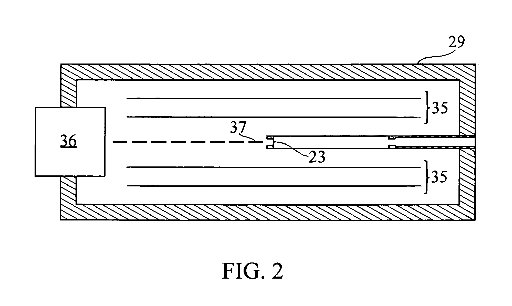
[0030]The solid state fusion device of the present invention includes a rectangular region of solid or powdered form reactant 20, into which ionic form reactant is fired longitudinally at fusion energies. Preferably this region will have a height much less than its width or depth. In one embodiment this region is placed between two thin conductive plates 21, and an insulating frame 22 is provided to separate the plates and allow solid form fuel to be contained within the resultant structure. A thin conductive window 23, electrically connected to the two conductive plates, is then provided in the insulating frame. Additionally, a plurality of filtered ports are provided in the insulating...


PUM


Abstract

By firing ionized reactant particles into a solid block of reactant, fusion reactions occur. As these particles are fired longitudinally into a thin sheet of reactant, fusion products are ejected laterally into a series of charged collectors. Unfused reactant ions that prematurely exit the solid reactant are recirculated by electric fields within the invention, boosting efficiency. Through the use of several collectors, charged particles of many energies are efficiently collected and converted to electric potential. The use of a solid sheet of reactant greatly increases the probability of fusion events taking place. The shape of the sheet acts to isolate the incoming reactant ions from the outgoing fusion products. Fusion products are not generally converted to heat by virtue of the small amount of material present in a typical product trajectory. Singly and together, these improvements act to greatly increase the efficiency of the reactor over prior art.

Description

CROSS-REFERENCE TO RELATED APPLICATIONS[0001]I claim priority of Provisional Patent Application No. 61 / 339,787, filing date Mar. 8, 2010, “Method and Apparatus for the Production of Nuclear Fusion.”STATEMENT REGARDING FEDERALLY SPONSORED RESEARCH OR DEVELOPMENT[0002]Not ApplicableREFERENCE TO A SEQUENCE LISTING, A TABLE, OR A COMPUTER PROGRAM LISTING COMPACT DISK APPENDIX[0003]Not ApplicableBACKGROUND OF THE INVENTION[0004]Without limiting the scope of the invention, its background will be discussed within the framework of general nuclear fusion. Nuclear fusion is a highly desirable process, as it is capable of releasing significant amounts of energy and subatomic particles from the two reactants provided to it. These fusion products, such as neutrons, can be readily utilized for nuclear experiments and other scientific applications. Additionally, certain reactants release large amounts of charged particles when fused. These charged particles can be directly converted into electrica...

Claims


Application Information

Patent Timeline
Patent Type & Authority Applications(United States)
IPC IPC(8): G21B1/00G21B1/17G21B1/19
CPCY02E30/16G21B1/19G21B1/17G21B1/00Y02E30/10G21B3/006G21B1/11G21B3/00G21B1/03
Inventor PEARSON, TIMOTHY RAYMOND
Owner PEARSON TIMOTHY RAYMOND
Why Eureka
Try Eureka